
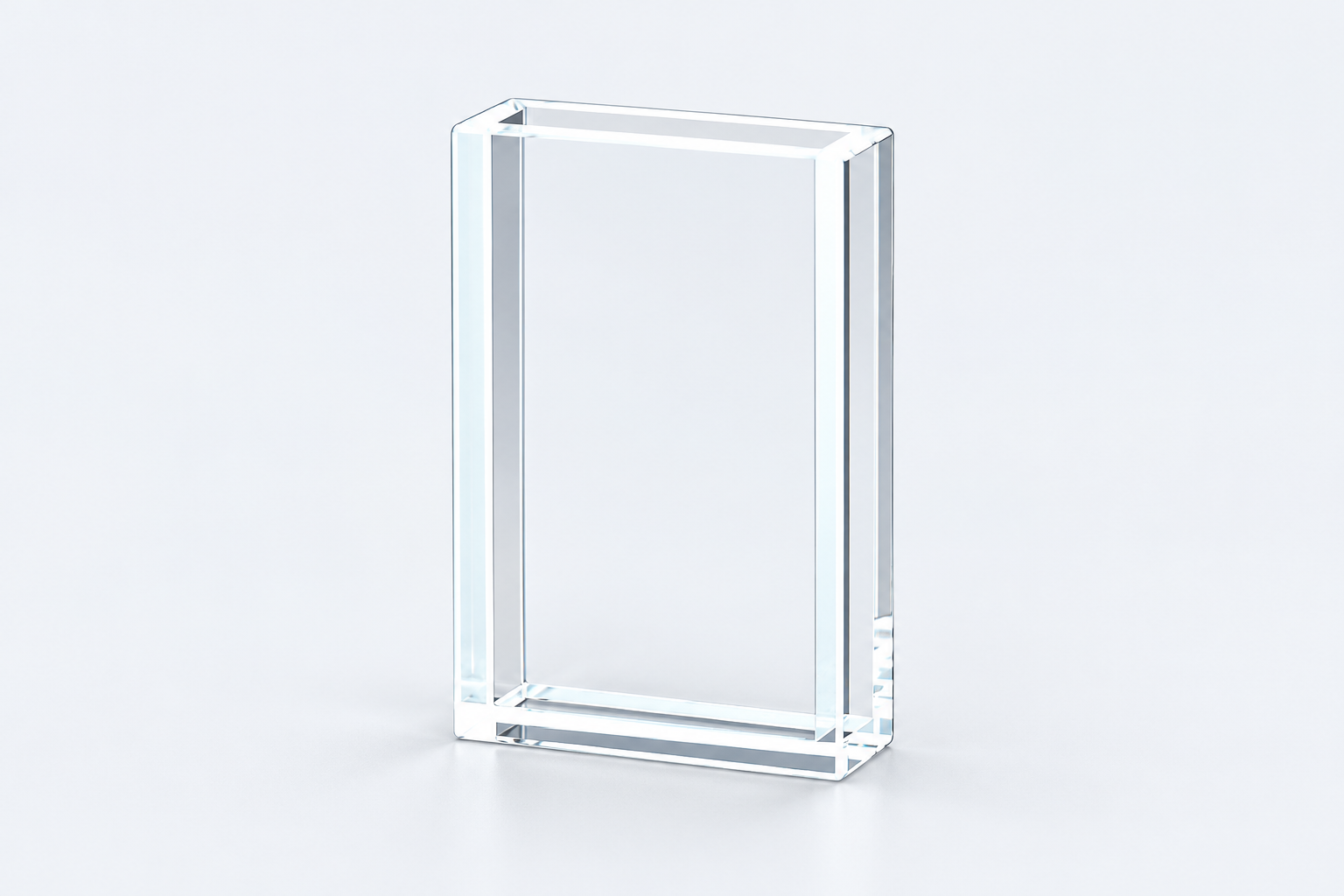
Quartz Cell for Contact-Lens Inspection: Loading and Viewing the Specimen
CUSTOM DESIGN GUIDE · MQQCU010
MQQCU010 is a quartz cell listed for contact-lens inspection, with 21 mm and 5 mm optical directions. Its wide, shallow chamber makes room for a specimen while offering different viewing distances. The useful starting question is how the lens will be placed, viewed and removed.
Use and purpose · Specifications · In practice · Custom example · Buy or enquire
Start with the specimen, not a cuvette size
A liquid-only measurement is often described first by path length. With a lens specimen, placement matters just as much: the part needs to enter the chamber and occupy the intended observation region. The open top supplies access for that loading step.
The reference has a 25 × 9 × 40 mm outside body, 2 mm walls and five-face optical access. Its 21 mm and 5 mm chamber directions describe two routes through the same sample space. They are not two separate compartments.

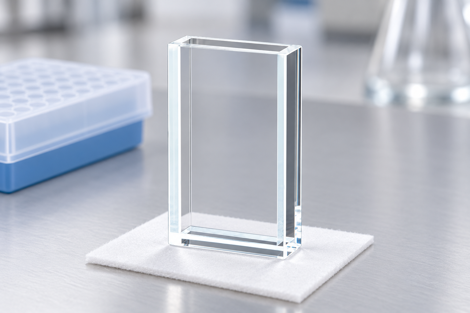
MQQCU010 configuration
Use the two directions to describe the inspection layout
A drawing can show the specimen in the chamber, then add the illumination and observation directions around it. The wide direction and the shallow direction play different roles depending on that arrangement. Rotating the cell changes their relationship to the instrument.
Five available optical faces are useful only where the support leaves the required routes exposed. A retaining plate beneath or beside the cell can cover one of those faces, so the holder and specimen should appear together in the inspection sketch.
Leave room for the loading tool
The top opening is part of the handling route, not merely the top edge of the product. A tool that places the lens may need more room than the lens itself. The same applies when lifting a specimen out of liquid after observation.
This form is a starting point for a specimen-centred setup. It is not an asserted fit for a named inspection instrument: the relevant design inputs are the specimen envelope, its desired position, the optical directions and the actual loading tool.
A custom example: increase access without changing the viewing paths
ILLUSTRATIVE DESIGN EXAMPLE
Suppose the 21 mm and 5 mm chamber directions suit the inspection, but the tool approaches the opening at an angle. A proposed change can concern the opening or surrounding support region while keeping the useful optical space. This focuses the design on the handling limitation rather than enlarging the entire cell.
Order the listed configuration or discuss a change
View MQQCU010 and current pricing. For a custom version, send a labelled sketch that separates the features to retain from the changes you want.
For MQQCU010, include a specimen outline, its intended position, the loading tool and the light directions. Mark the optical dimensions to retain and the access to change. Add the sample medium, quantity, destination and requested date.



Recent Comments