
Oval-Region Quartz Flow Cell: A Broad Viewing Layout with Side Connections
CUSTOM DESIGN GUIDE · MQQFC140
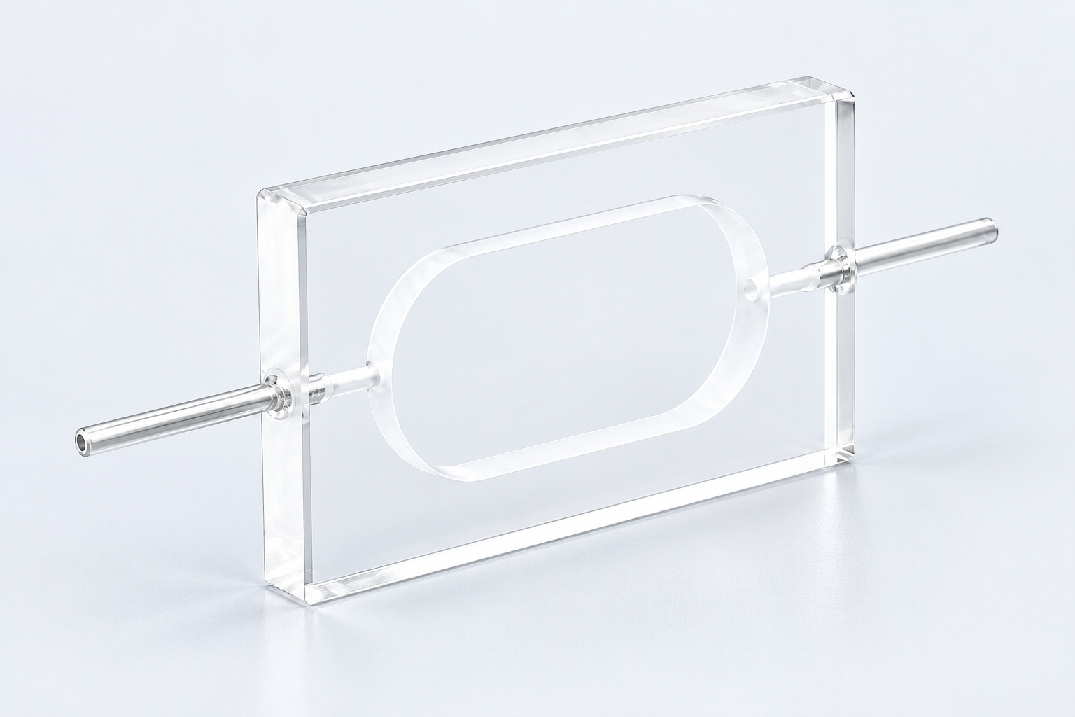
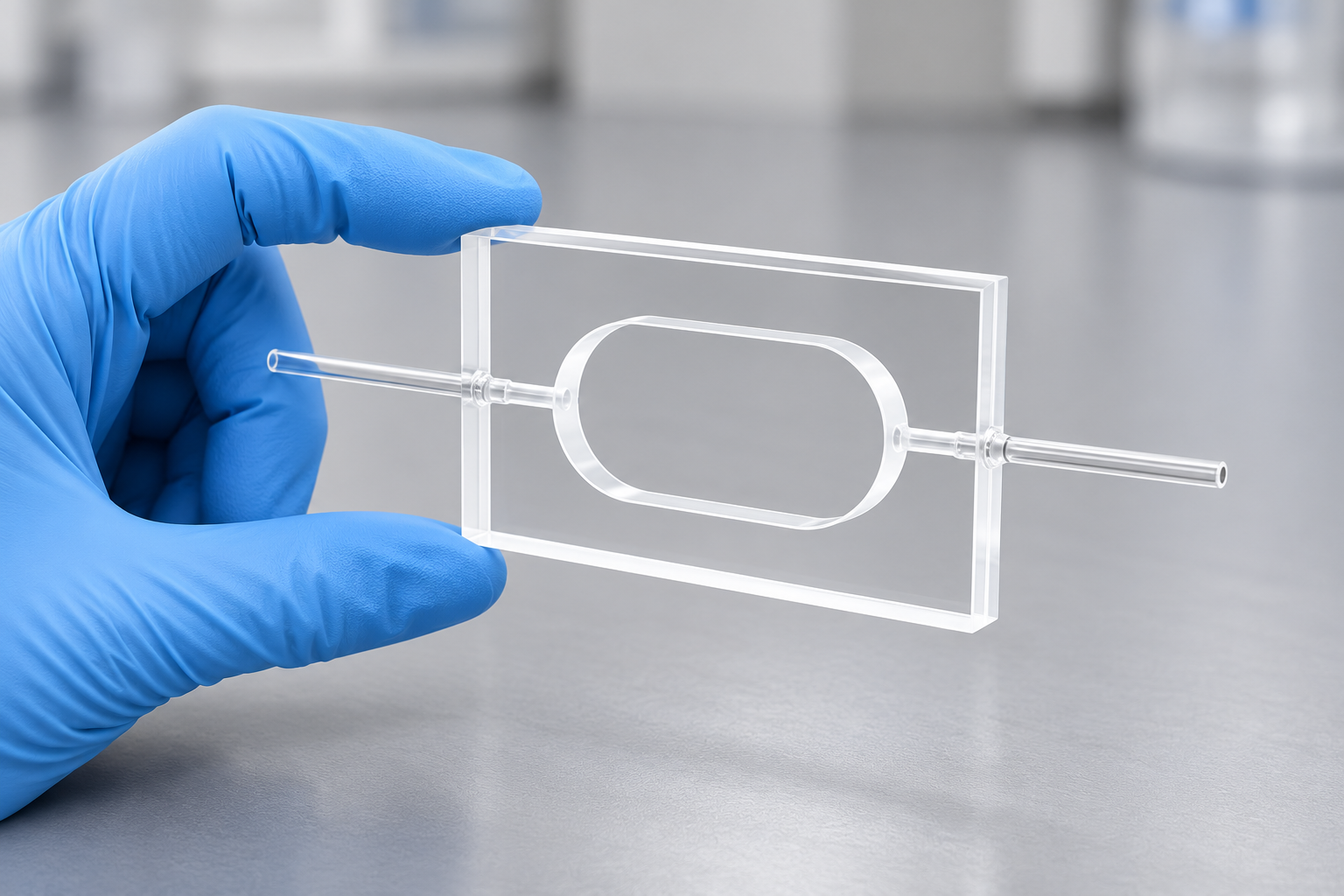
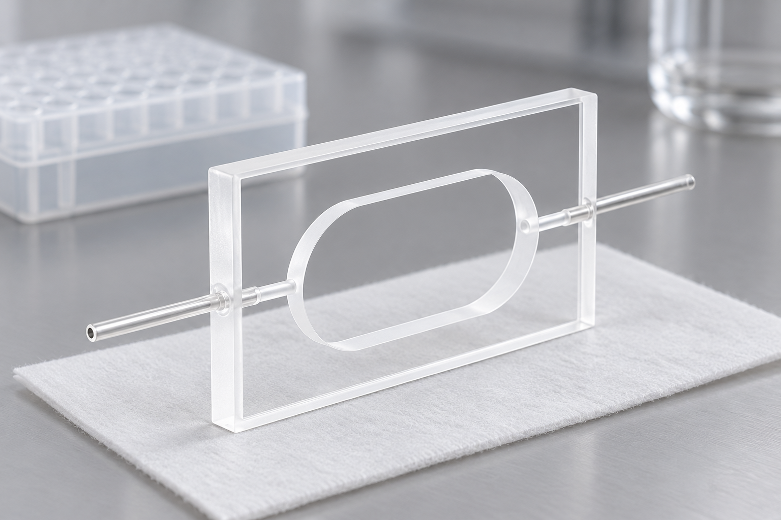
MQQFC140 places an elongated oval viewing region in a flat quartz body, with a tube approaching from each side. Its 5 mm path and broad outline make it a reference for a connected observation area that is shaped differently from a small square cuvette window.
Use and purpose · Specifications · In practice · Custom example · Buy or enquire
Define the field inside the oval
The oval outline identifies the sample region within a 60 × 6.3 × 35 mm body. The outside rectangle is useful for positioning; the region inside it is useful for the observation. A broad outside face does not make every part of that face a sample-filled viewing area.
For a proposed camera, scanning beam or other observation layout, the required field can be drawn inside the oval. That shows whether the shape actually serves the method. The 5 mm path describes another direction through the sample and remains independent of the field's width.
MQQFC140 configuration
The side connections change how the region is approached
The two opposed tubes have a 2 mm outside diameter and 1 mm bore. They bring sample access to the sides of the flat body, while observation uses the central region. A support can surround the body border without occupying either the useful view or the connection approaches.
The complete fluid route includes the mating connectors and attached lines. Their outlines may be larger than the tube ends, so they belong in the same view as the holder rather than being treated as details outside the cell design.
A wider region needs a purpose
The oval form is worth considering when the method benefits from that observation outline. If only a small central point is used, the wider body may add mounting space without adding a useful sample view. The field, not the product silhouette, gives the custom region its shape.
Loading and exchange should be described around that field. The proposed routine needs to bring sample to the region being observed, rather than just move liquid from one external connector to the other.
A custom example: reshape the region around the required field
ILLUSTRATIVE DESIGN EXAMPLE
Suppose a proposed observation field is wider or lies elsewhere within the available mounting space. A new layout can retain the 5 mm path and define the sample-region outline from that field. The support border and opposed connections are then placed around the required region.
Order the listed configuration or discuss a change
View MQQFC140 and current pricing. For a custom version, send a labelled sketch that separates the features to retain from the changes you want.
For MQQFC140, draw the observation field and sample-region outline inside the available holder envelope. Identify the path to retain, tube approaches and loading routine. Add sample conditions, quantity, destination and requested date.


Recent Comments