
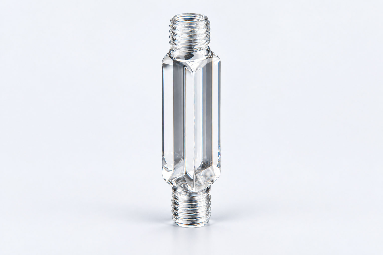
4 / 10 mm Dual-Path Quartz Flow Cell with Opposed Connections
CUSTOM DESIGN GUIDE · C044TS
C044TS combines two optical path directions, 4 mm and 10 mm, with opposed M12 threaded openings. It provides a reference for a connected sample chamber whose viewing orientation matters as much as its fittings. The paths and the ports describe different parts of the same cell.
Use and purpose · Specifications · In practice · Custom example · Buy or enquire
Choose the measurement direction independently of the fluid route
A dual-path chamber offers different sample distances along different viewing directions. In absorption work, that can be useful when evaluating path length at a given sample concentration. The 4 mm and 10 mm values do not imply two independent fluid channels. [1]
A beam sketch establishes the required viewing direction; a fluid sketch identifies the opposed connections. The two drawings become one installation layout when they share the holder datum and the intended orientation of the body.
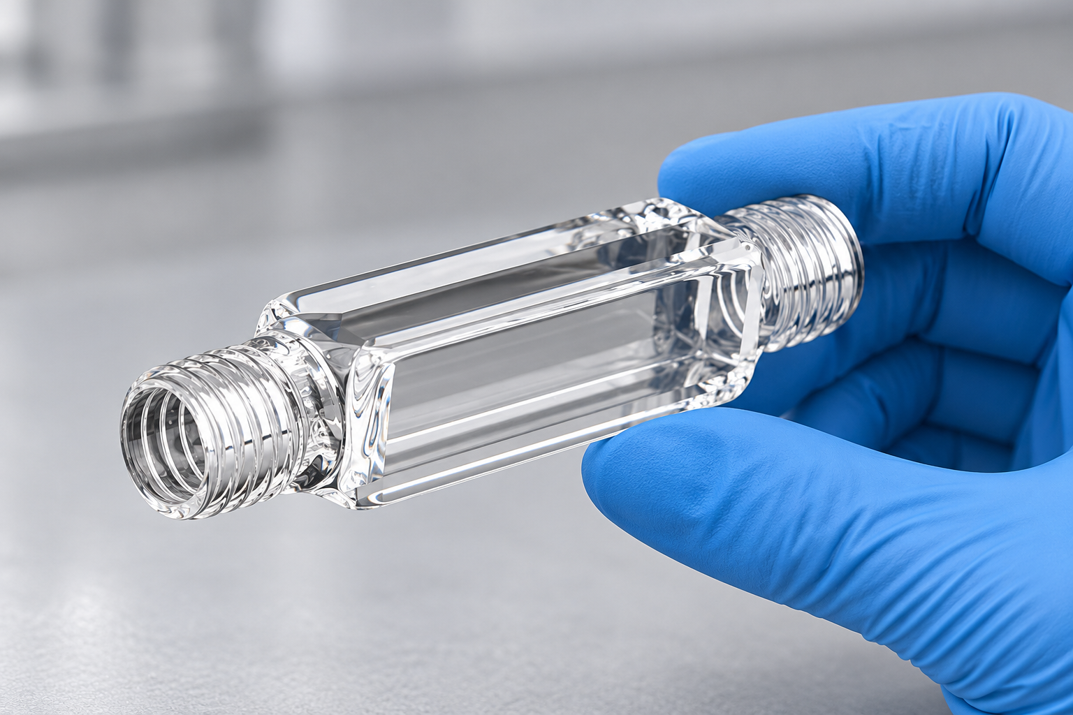
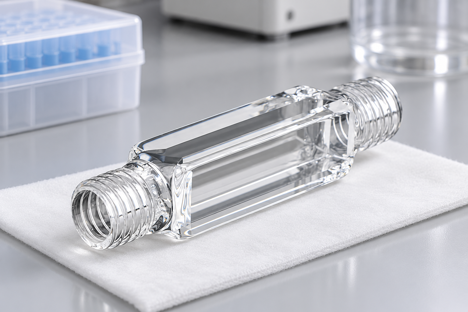
C044TS configuration
The threaded openings add access at both ends
The recorded body has a 12.5 × 12.5 mm base and 40 mm height, with nominal 1.4 mL capacity. Those dimensions describe the central cell. Mating fittings, seals and tubing extend beyond it and need space for connection and removal.
An M12 label identifies a thread family. The mating thread and sealing contact complete the interface. A compact bracket can clear the body yet prevent a fitting from being turned, so working clearance deserves its own outline on the assembly drawing.
Make the connected chamber usable between measurements
The supply route, chamber and outlet together determine how liquid enters and leaves. Tubing also holds sample, and flushing adds to the amount used. A 1.4 mL nominal chamber is therefore different from a complete system requiring only that volume.
If the cell is removed frequently, the removal sequence matters: fittings may need to be released before the body can leave the holder. Designing that sequence is often more useful than shrinking the body while retaining inaccessible connections.
A custom example: preserve the paths and change one fitting approach
ILLUSTRATIVE DESIGN EXAMPLE
Suppose the optical layout uses the 4 mm direction, but one end connection faces a wall. A proposed connection arrangement can keep both chamber directions and move the obstructed interface. The drawing then defines the fitting envelope, beam route and removal access together.
Order the listed configuration or discuss a change
View C044TS and current pricing. For a custom version, send a labelled sketch that separates the features to retain from the changes you want.
For C044TS, mark the optical direction in use and supply both mating fitting drawings. Include the holder, sealing contacts, tubing approach and sample procedure, then add quantity, destination and requested date.


Recent Comments