
0.2 mm Quartz Flow Cell: Routing Both Connections from One Face (MQQFC114)
Custom design guide · MQQFC114
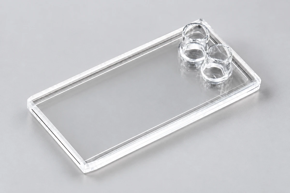
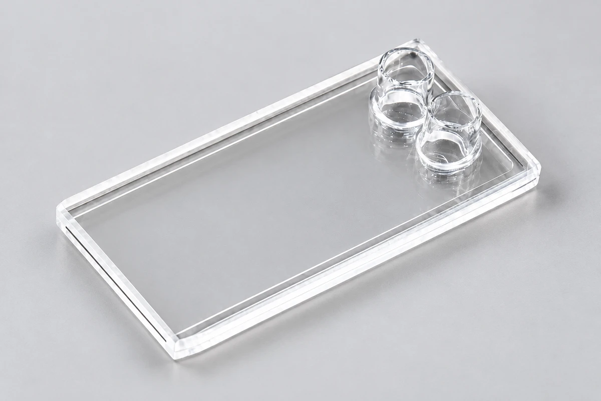
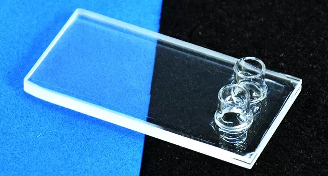
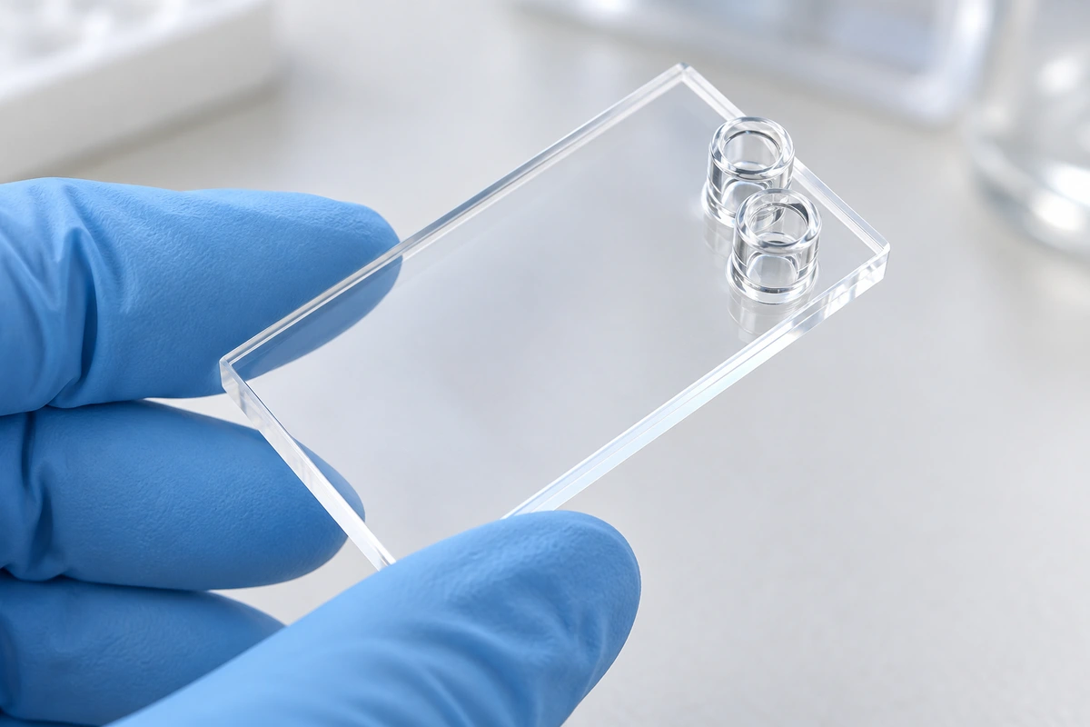
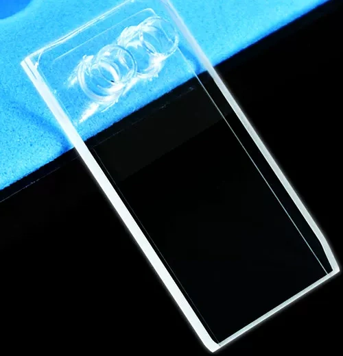
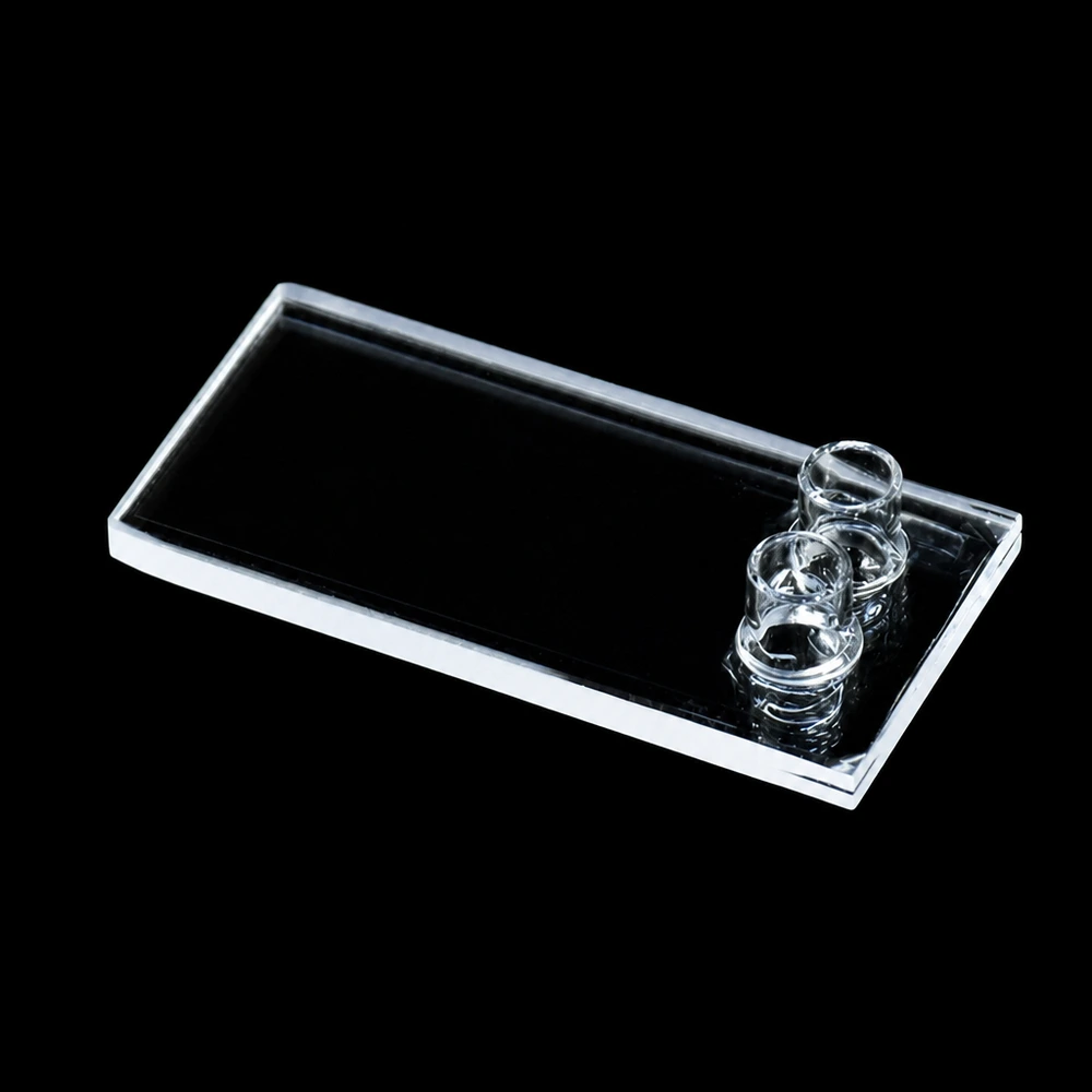
MQQFC114 has a nominal 0.2 mm path and 120 µL capacity, with both tubes emerging from one broad face near an end. This arrangement brings the connections to the same side of a thin body, making connector space and clear optical access closely related choices.
The situations and proposed changes below are planning examples, not completed customer projects.
Structure and use · Current specifications · Selection details · Proposed changes · Before ordering · Buy or enquire
Choose the layer thickness and connection side together
If a longer cell gives absorbance outside the instrument's useful range, a shorter path may be one option to assess alongside sample dilution. Under Beer–Lambert conditions for a homogeneous solution, reducing the path reduces absorbance at the same concentration and wavelength. MQQFC114 supplies a nominal 0.2 mm layer; selecting it still requires the actual sample and instrument conditions.
The second choice is where the tubing can go. Both connections approach from the same broad face near one end, which may suit a proposed enclosure with access on that side. Draw the fitted connectors beside the beam and holder: easier routing is only useful if the measurement region remains accessible.
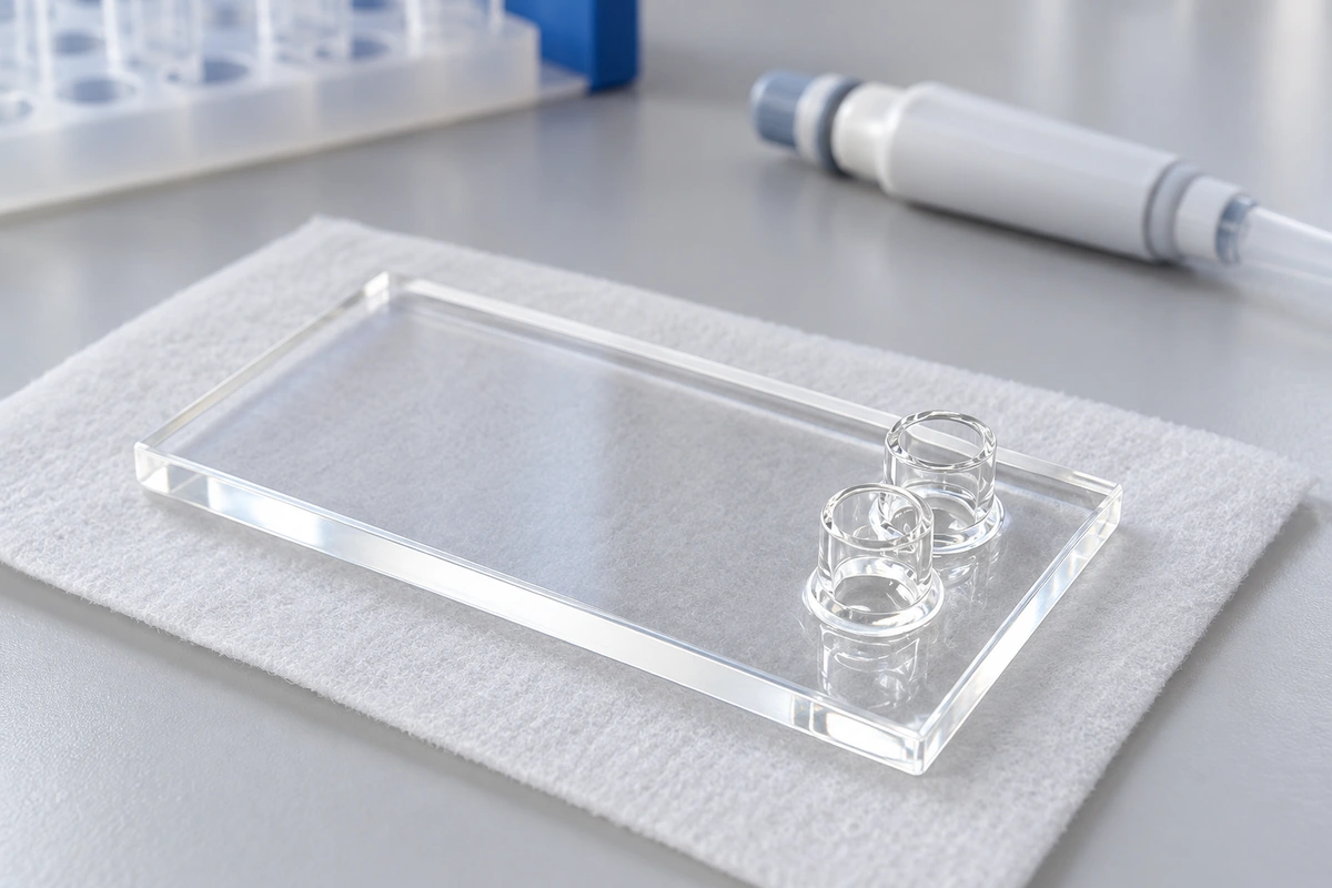
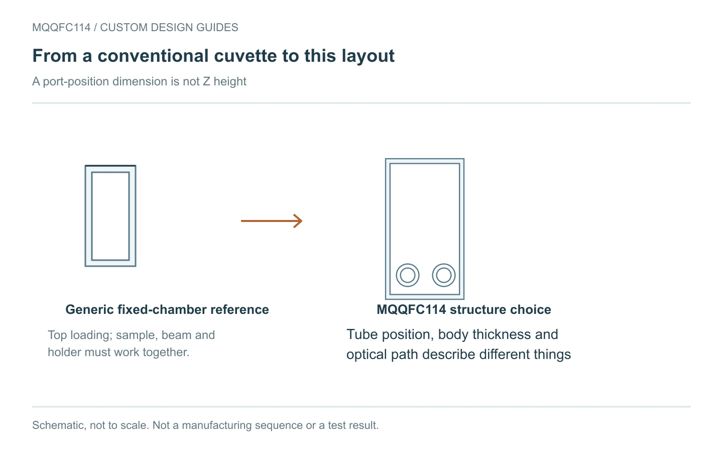
Current MQQFC114 configuration
Open engineering reference R01 and PDF
Source-based dimensions and configuration for discussion. Unconfirmed geometry and tolerances remain to be agreed; this is not a manufacturing-release drawing.
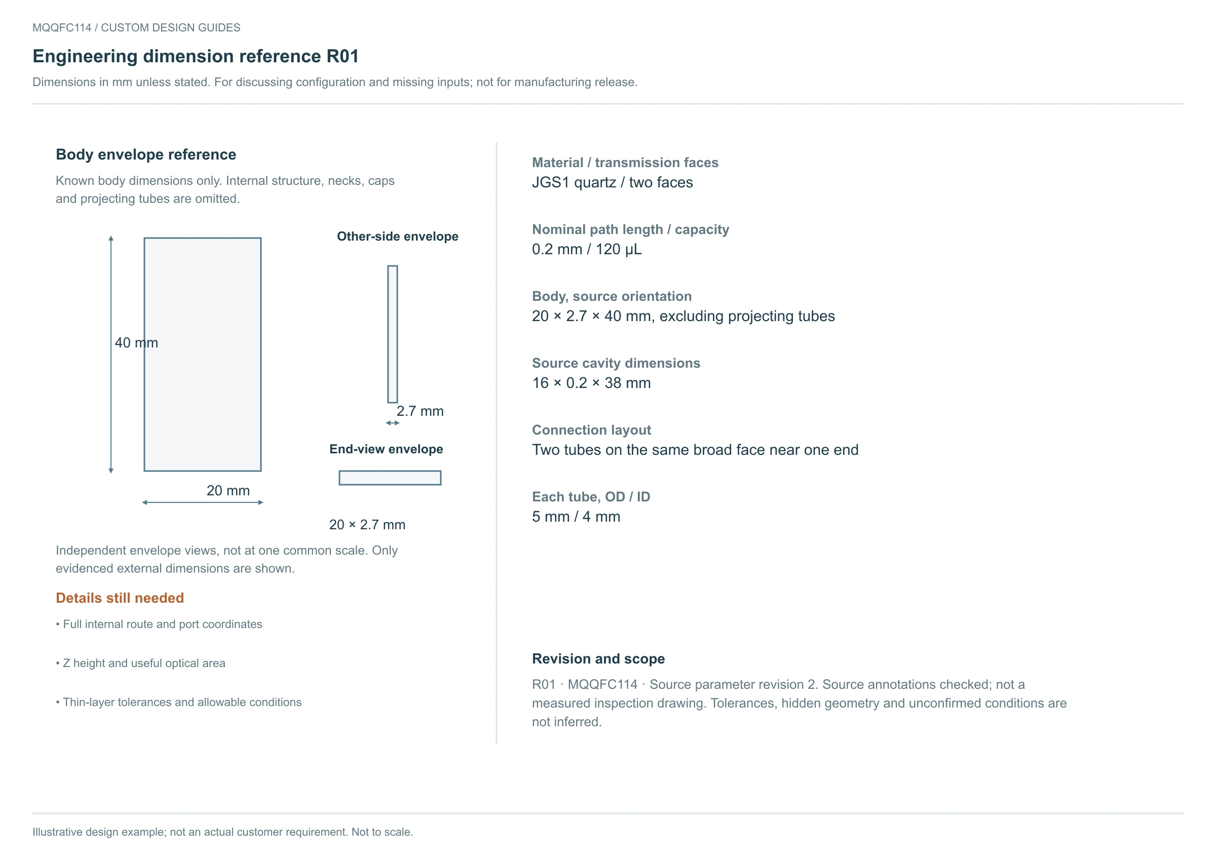
View full-size engineering reference · Download the complete English engineering reference PDF
Allow for the connectors beyond the thin body
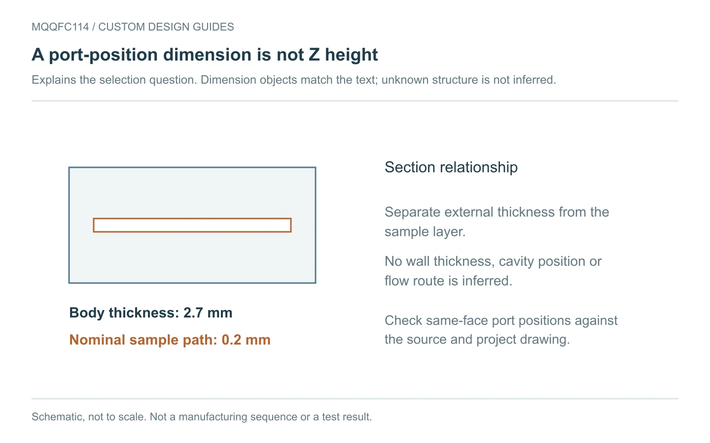
The optical body is 20 × 2.7 × 40 mm, excluding its projecting tubes. Each tube is 5 mm OD / 4 mm ID, so a body-only thickness check misses the larger connection envelope.
The source's 5 mm edge offsets locate the port centres. They do not locate the optical beam. Name the edge datums and beam position independently when specifying a holder or revised port layout.
Check filling in the chosen orientation
For a proposed filling trial, show the installed orientation and label the intended inlet and outlet. Observe whether bubbles remain in the thin region and whether the previous sample clears during flushing. The 16 × 0.2 × 38 mm source cavity and nominal capacity describe the cell; exchange time also depends on the medium and complete fluid circuit.
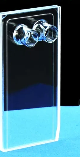
View another product angle
Keep the short path and move the ports
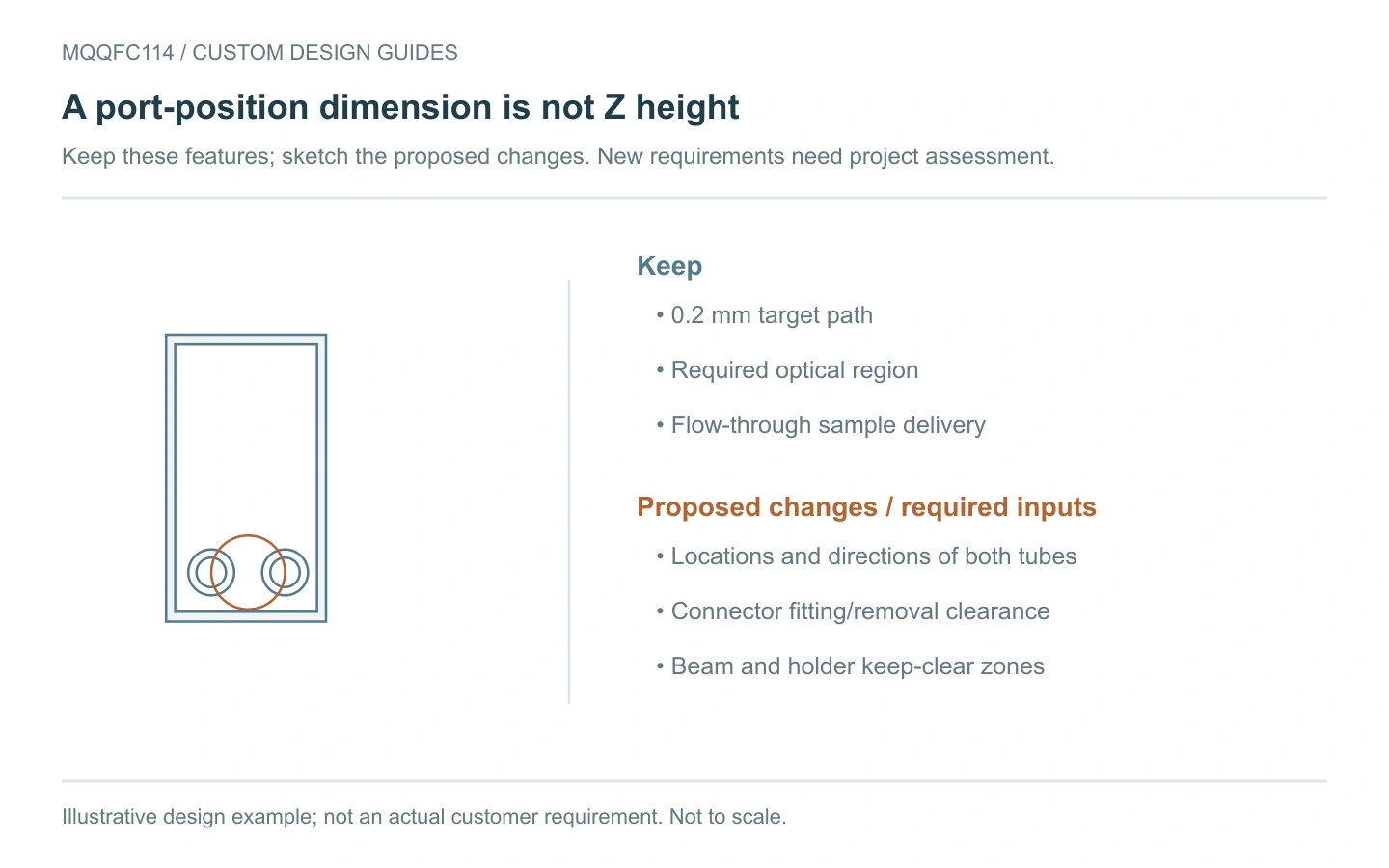
If the 0.2 mm target path suits the method but fitted connectors meet the holder, mark proposed port centres from explicit body edges. Add the actual connector outline and hose approach.
We need to review the cavity and connections together. Include the desired optical region and sample conditions so that a revised port position is assessed as part of a complete cell design.
Checks to agree before ordering
- Layer: Identify the path-length object and agree any requested dimensional check.
- Clearance: Check ports, fitted connectors and hoses against both holder and beam.
- Filling: Review bubble removal, residue and exchange with the intended orientation and conditions.
Sample and cleaning conditions
Agree sample and cleaning conditions for the complete item, including wetted caps, seals and fittings. Give chemical identity, concentration, temperature and contact time. Avoid hydrofluoric acid; strong alkalis, heat and prolonged exposure also need review. A JGS1 material label alone does not establish suitable operating conditions.
Order this configuration or discuss a change
View MQQFC114 specifications and current pricing. If you need a delivery date, ask about availability and preparation or production time before ordering.
For a modified version, send the brief below with a dimensioned drawing or labelled sketch. We review the proposed configuration and confirm feasibility, quantity, inspection scope, pricing and production time in the quotation.
Copy this custom-enquiry checklist
Reference SKU: MQQFC114
Keep: 0.2 mm target path; proposed port centres from named edges: ____
Beam/optical region, holder and connector outlines: ____
Sample, orientation, inlet/outlet, filling/flushing, flow and pressure: ____
Sample and cleaning liquids, concentrations, temperature and contact time: ____
Wavelength, critical tolerances and required inspection/documents: ____
Quantity, required date and destination: ____
Send your sketch and requirements. Mark the features to keep and the changes to assess.
Technical reference
Configuration reference: MQQFC114 product specifications. Specifications checked 26 October 2026. General principles guide selection; they do not establish measured performance of this cell.
For the absorption principle, see the IUPAC Gold Book: Beer–Lambert law.


Recent Comments