
Flanged Quartz Flow Cell: Joining a Square Optical Chamber to a Fluid Line
CUSTOM DESIGN GUIDE · MQQFC070
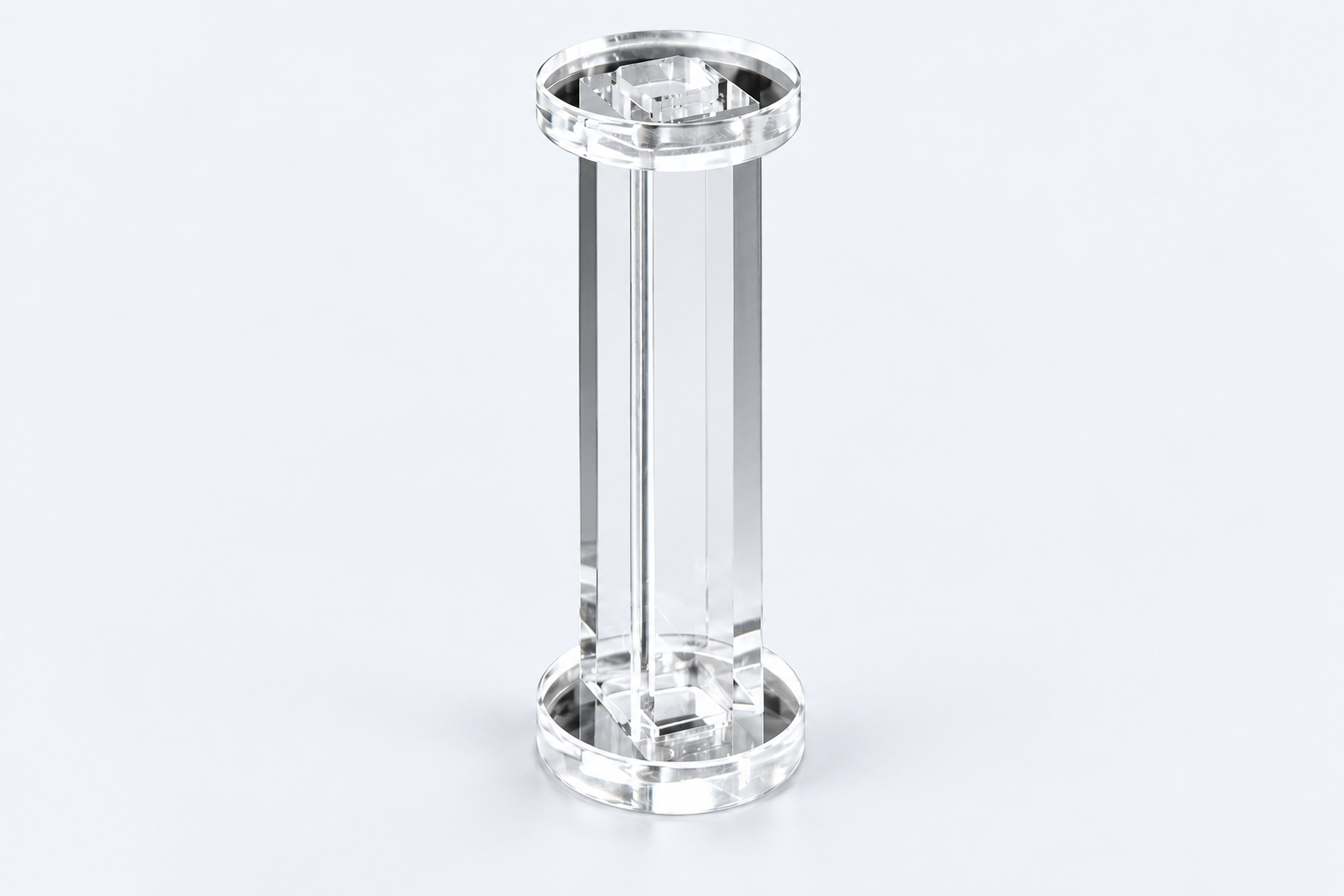
MQQFC070 combines a square quartz sample chamber with circular flanges at both ends. The reference has a 10 mm path, nominal 10 mL capacity and 100 mm overall length. Its form separates the central viewing region from the end interfaces used by a proposed connected assembly.
Use and purpose · Specifications · In practice · Custom example · Buy or enquire
A viewing chamber between two end interfaces
The central section is 16 × 16 mm outside and 10 × 10 mm inside, with four-way optical access. The end flanges are 30 mm outside diameter. The result is a narrow square centre with wider circular regions at the ends.
Compared with placing a plain cuvette in a holder, a flanged design brings the connection interface into the cell geometry. It is relevant where an instrument or sample line needs an optical chamber between mating end parts, while leaving the central faces available for observation.
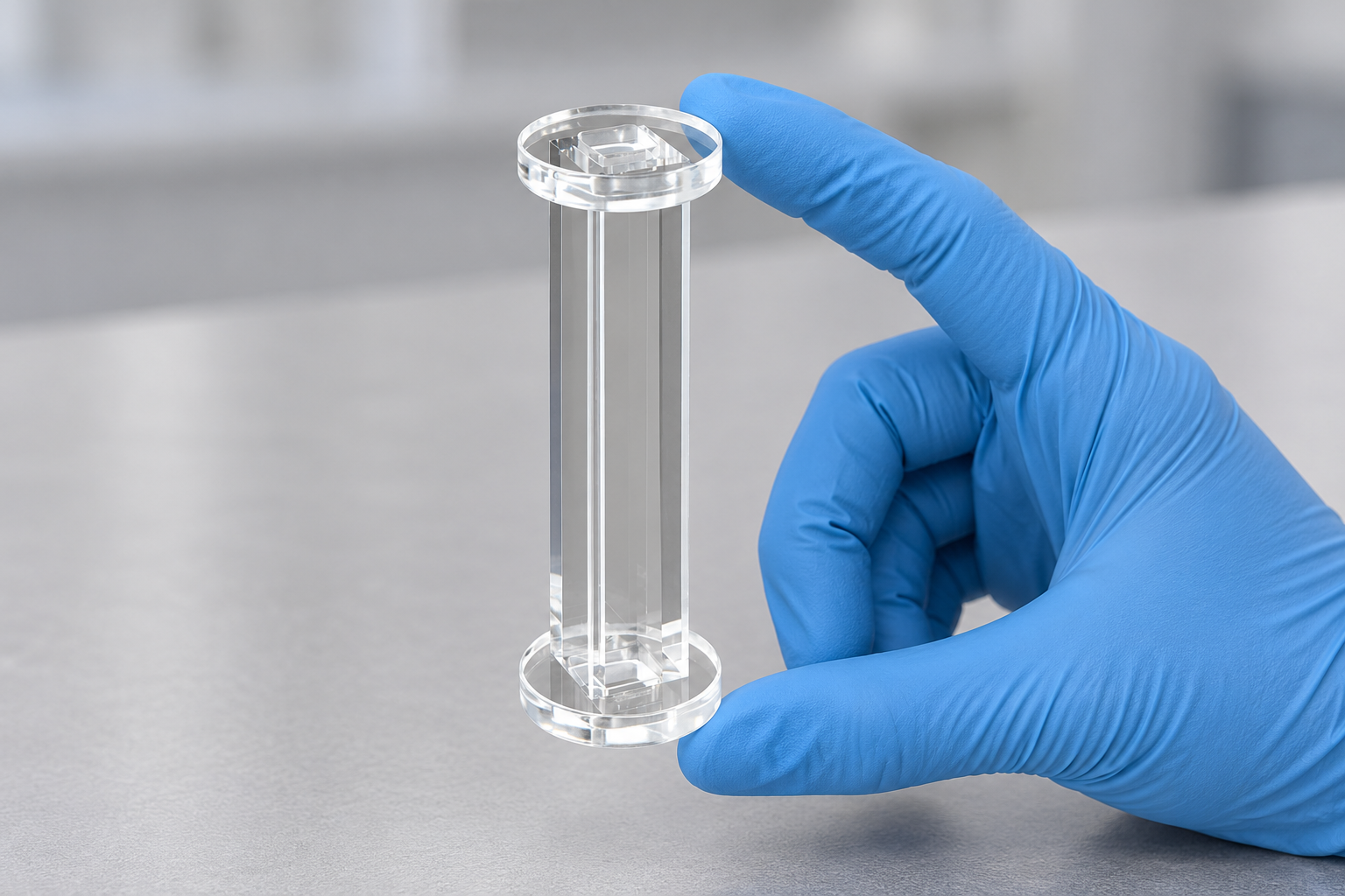
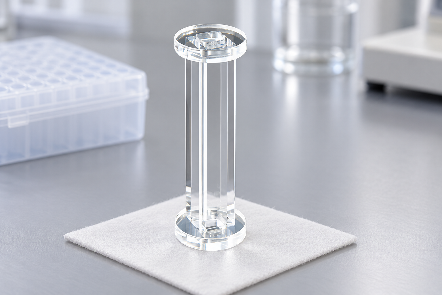
MQQFC070 configuration
The seal contact is more specific than the flange diameter
A 30 mm outside diameter describes the flange envelope. The mating surface, locating features and sealing contact describe how an end part actually meets it. Those details can differ between assemblies with the same nominal outside diameter.
The support and connection hardware should also leave the viewing section clear. A flange can be mechanically accessible while a nearby retaining part covers the optical route. Showing both end contacts and the intended observation area makes that conflict visible.
Separate chamber length from installed length
The reference labels 88 mm along the body region and 100 mm overall. These dimensions locate different boundaries. The installed outline grows again when mating parts and tubing are added.
The operating conditions belong to that connected system. A flange shape does not establish a pressure or leak rating, and nominal cell capacity does not account for liquid in the rest of the line. The useful design brief covers the optical chamber, its two interfaces and the actual sample route.
A custom example: reuse an existing end assembly
ILLUSTRATIVE DESIGN EXAMPLE
Suppose a system already has two mating end parts, but needs a square optical region between them. A proposed cell can retain the useful chamber and define each flange from the existing mating drawings. This targets the contact and sealing geometry rather than merely requesting a different flange outside diameter.
Order the listed configuration or discuss a change
View MQQFC070 and current pricing. For a custom version, send a labelled sketch that separates the features to retain from the changes you want.
Reference MQQFC070 with both mating end drawings, support locations and the required optical routes. Include the sample line and operating conditions, then add quantity, destination and requested date.


Recent Comments