
M6 Quartz Flow Cell: Leaving Room for Both Connections (MQQSC042)
Custom design guide · MQQSC042
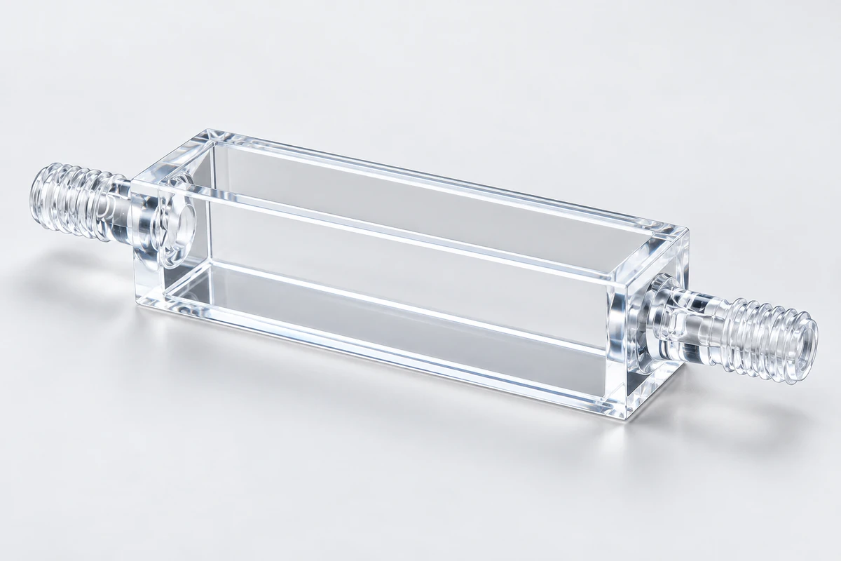
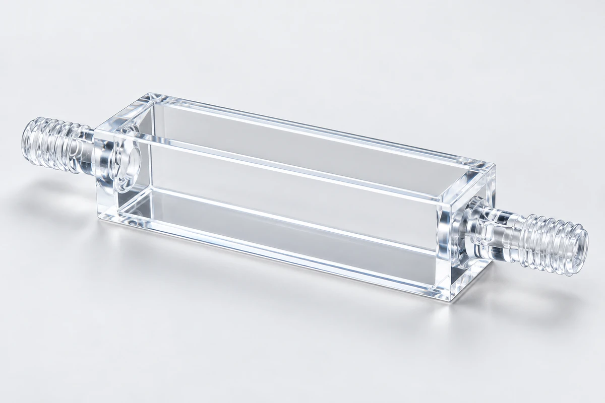
Opposed male M6 threaded ends connect a 10 mm-path optical body to a fluid route. Check the space occupied by the complete fittings and hoses, not just the rectangular body.
The situations and proposed changes below are planning examples, not completed customer projects.
Selection · Configuration · Structure · Custom version · Fit and use · Drawing · Enquiry
Leave room for the connections as well as the cell
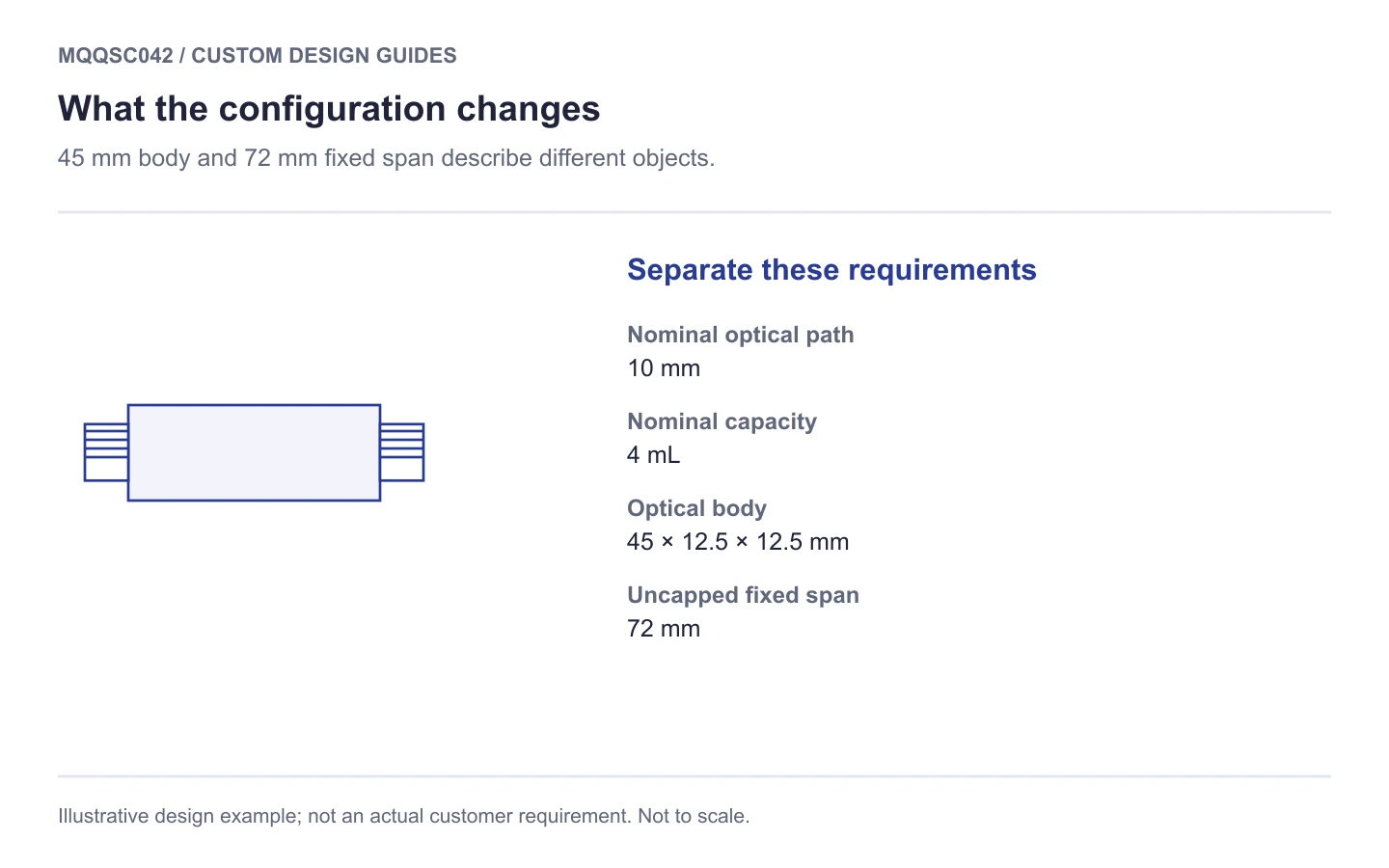
A flow cell can fit between the optics and still be impossible to connect inside the instrument enclosure. MQQSC042 illustrates that distinction: its body is 45 mm long, while the uncapped fixed span is 72 mm. Fittings and hose bends add to that envelope.
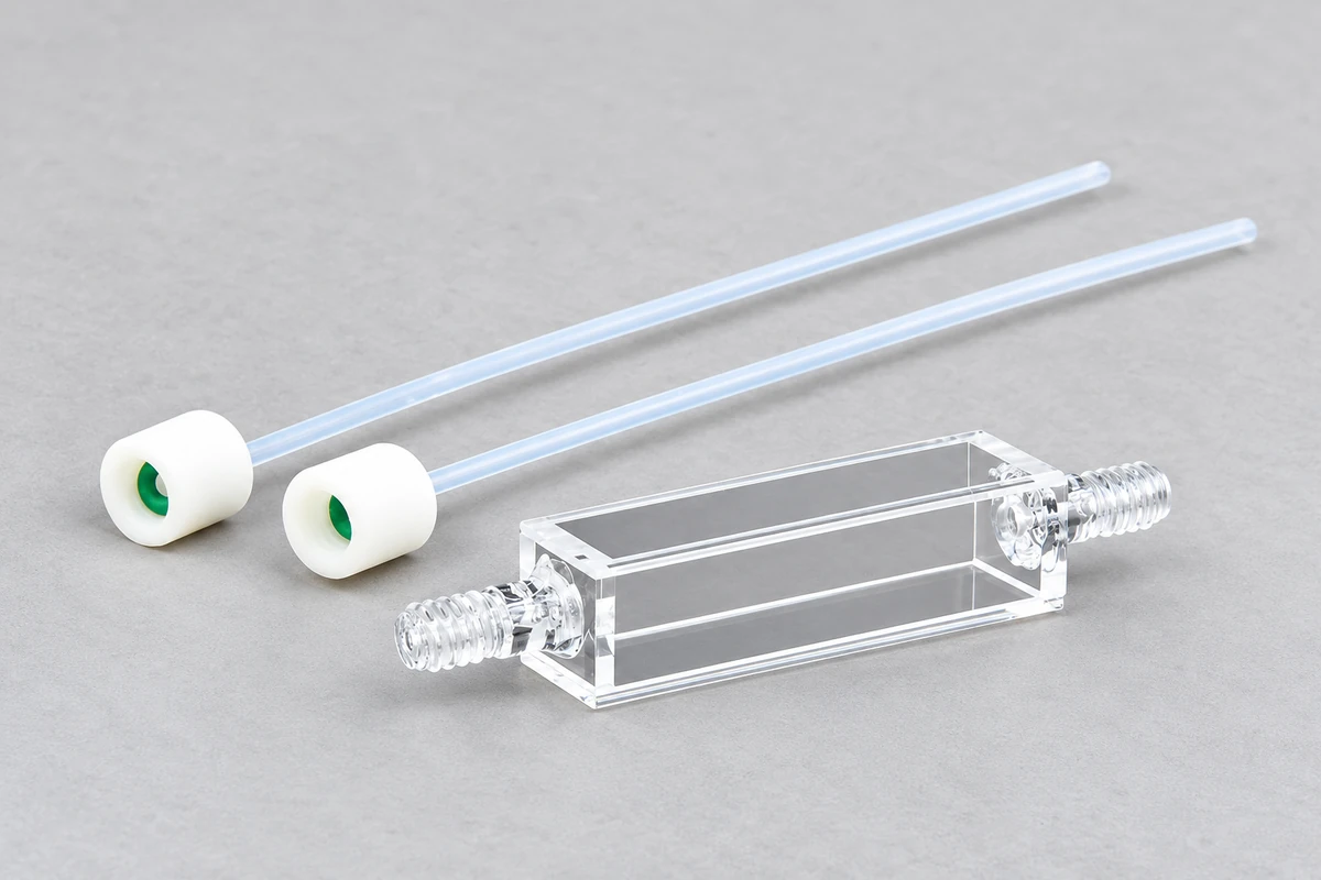
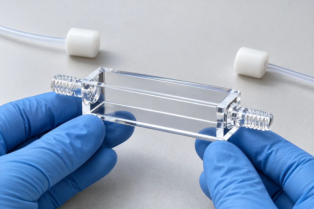
The two male M6 threaded ends provide connection points on opposite sides of the chamber. This is a configuration to assess when a sample needs to be delivered through tubing while the optical body stays in position. The connection pieces shown in the reference image help explain the arrangement; confirm the required fittings in the quotation.
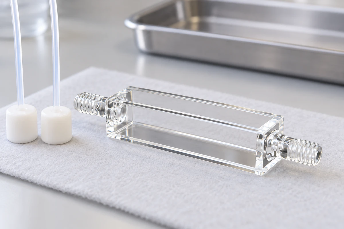
The listed configuration
View the selection schematic
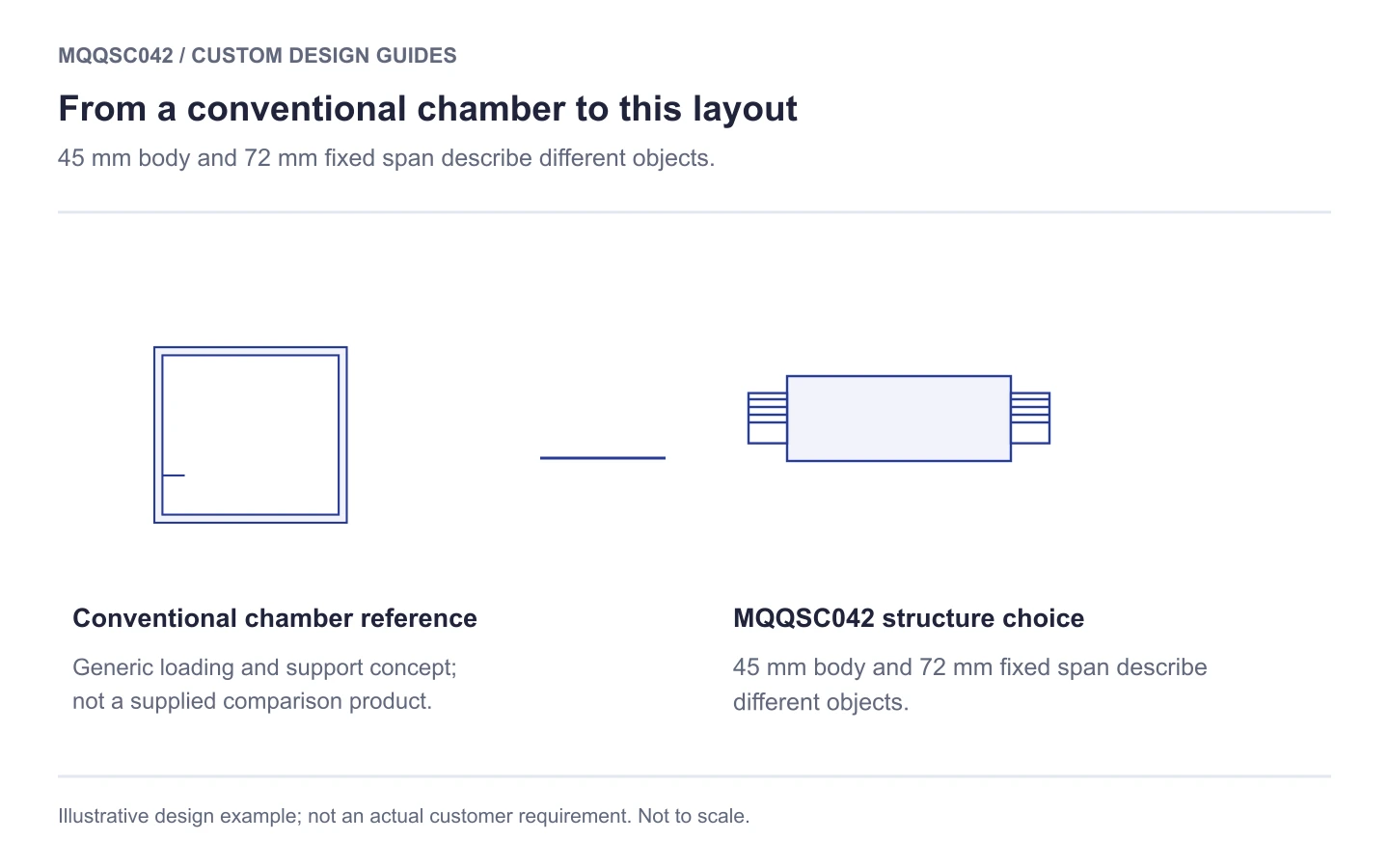
How the structure differs from a conventional cell
Adding end connections to a top-loaded cuvette changes both sample delivery and installation. The beam still has to pass through the specified 10 mm sample path, while the longer mechanical span must fit around the holder. Four transmission faces give possible optical directions, subject to the clear space left by the actual support and instrument.
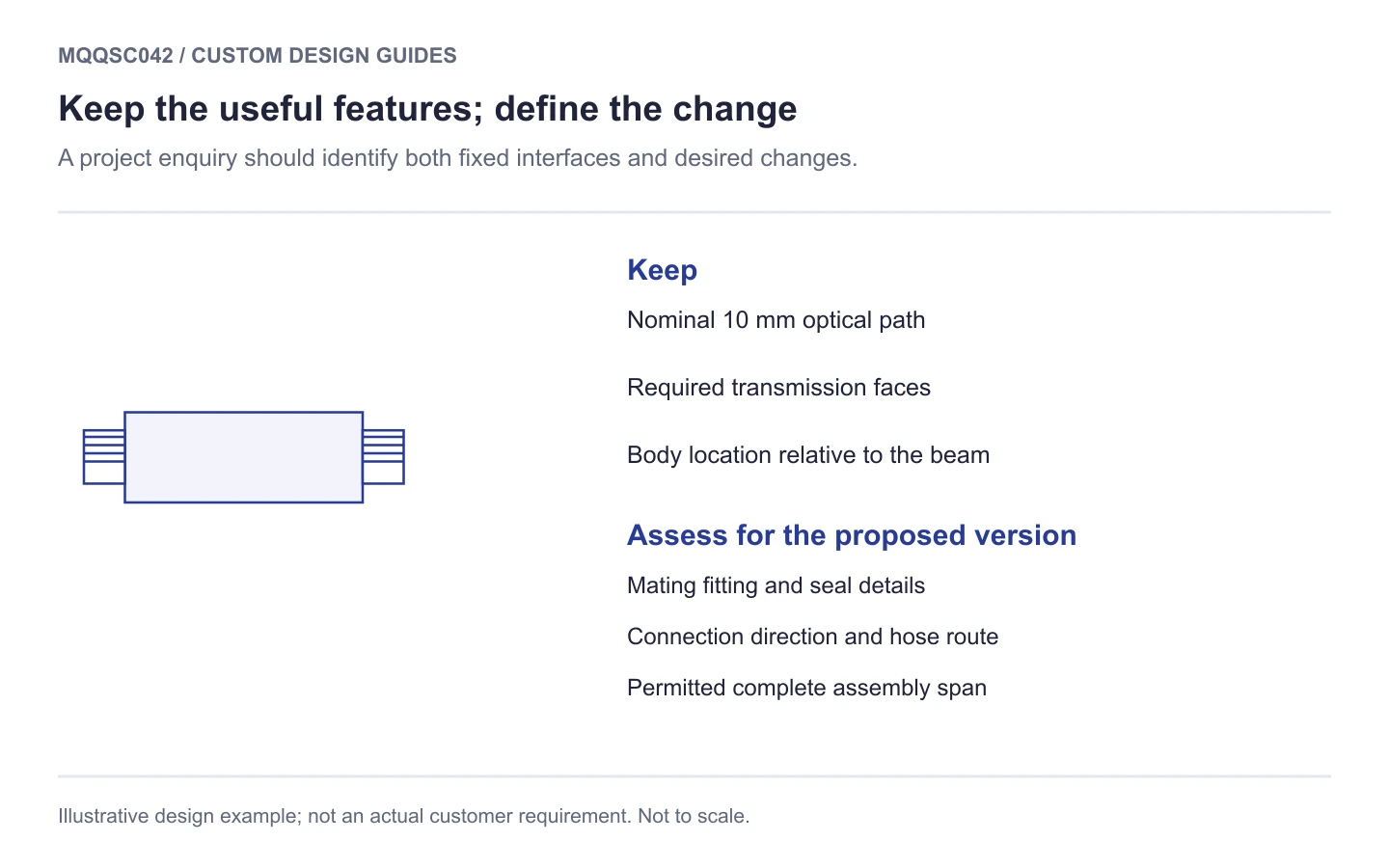
Decide whether the obstruction is a fitting or the cell
Start with the parts that already fit: the optical body, its support and the beam position. Then add the mating fitting drawing, seal seat, thread engagement and hose route. We can review a connection change against those fixed requirements.
A different hose route or shorter fitting may avoid changing the chamber. If the quartz ends need revision, also identify the sample region and optical position that must remain. Include enough clearance to fit and remove the connectors without using the cell as a lever.
View a custom-design discussion sketch
Three checks for the proposed setup
- Complete envelope. Draw both fitted ends, hose bends and the removal movement.
- M6 interface. Identify the actual mating part, engagement and sealing surface.
- Fluid conditions. State the medium, flow conditions, temperature and required leakage or pressure checks.
Plan an assembly check before fluid testing
Locate the body and support the hoses independently, then check access to each connector. Fitting or removing a connection should not twist the quartz body. Filling, flushing and leakage checks need an agreed procedure for the complete assembly; no operating-pressure limit is established by the available configuration information.
What information is needed to check my M6 fitting?
Send the fitting drawing or part specification, including thread engagement, seal seat, sealing components and wetted materials. M6 identifies a thread designation; it does not describe the whole fluid connection.
Engineering dimension reference
The reference records known external dimensions and configuration notes. Internal geometry, tolerances and operating limits still require a project-specific specification.
Open the engineering reference image
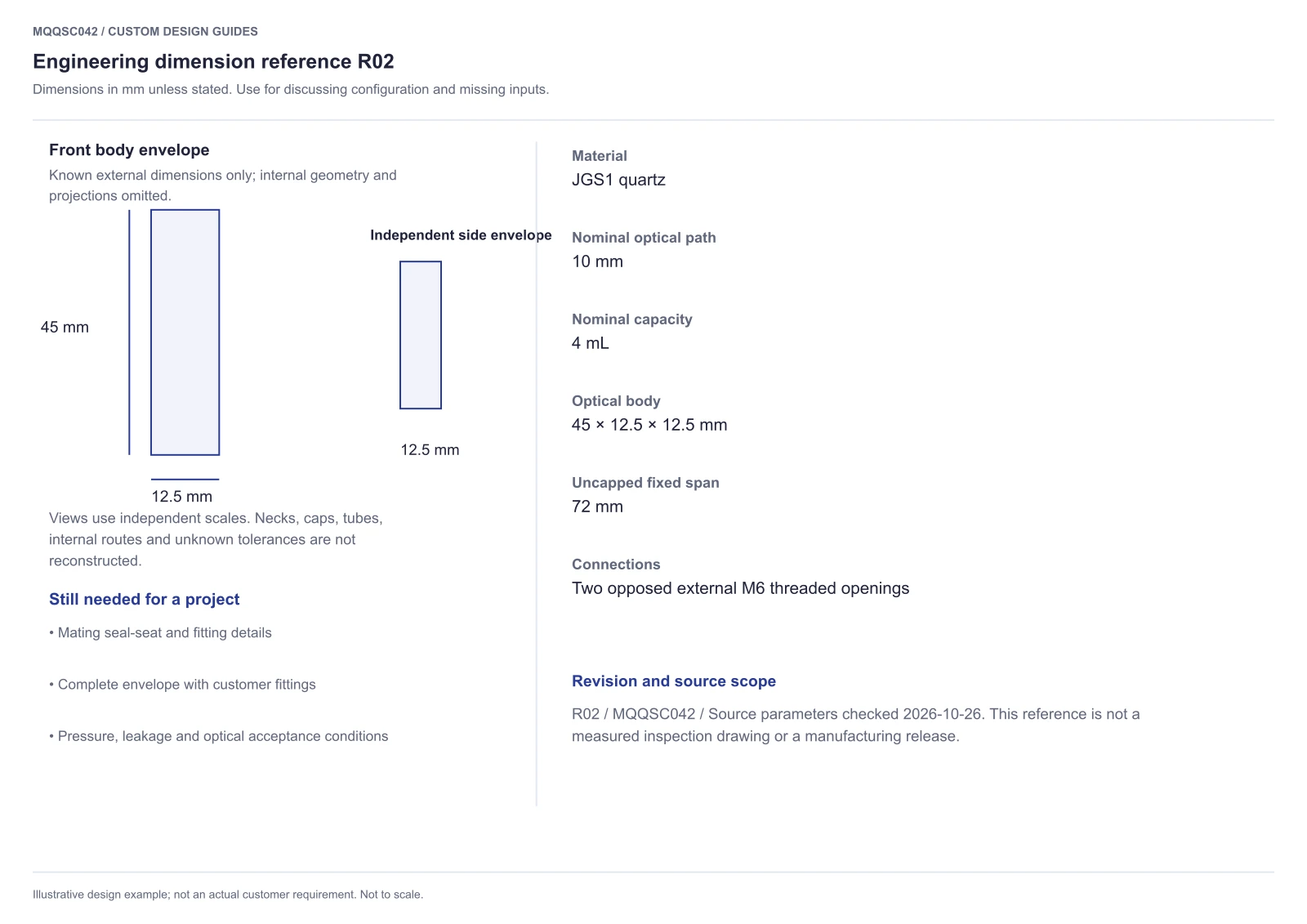
Download MQQSC042 engineering reference R02 (PDF). Illustrative design example; not an actual customer requirement.
Order this configuration or discuss a change
View MQQSC042 specifications and current pricing. Ask about availability and preparation or production time if you have a required delivery date.
For a modified version, attach a dimensioned drawing or labelled sketch. Contact MQ to review feasibility, quantity, inspection scope, price and timing for the proposed design.
Copy a starting brief for your enquiry
Reference SKU: MQQSC042
Keep the 10 mm path and holder contacts ___. Mating fitting drawing attached; maximum fitted envelope ___; hose route ___; medium and checks ___; quantity ___.
Attach your marked drawing and note any required inspection or documentation. Include the destination and target date so preparation, transport and customs can be discussed separately.
Send your sketch and requirements. Identify fixed interfaces and proposed changes.
Configuration and technical references
Configuration source: MQQSC042 configuration information. Listed parameters reviewed 26 October 2026.
Prepared for MachinedQuartz product selection and custom enquiries. MachinedQuartz is a US-based supplier established in New Mexico, USA, in 2026. Contact MQ. Custom cuvette enquiries · More design guides.


Recent Comments