
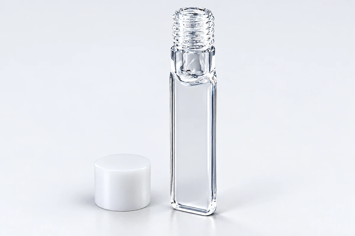
0.3 mm Screw-Top Quartz Cell: A Short Path Below a Wide Neck (MQQFL034)
Custom design guide · MQQFL034
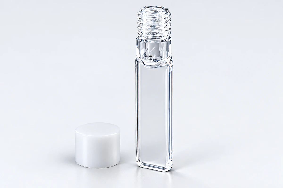
A nominal 0.3 mm sample layer sits below a larger M10 screw opening. The short path, thin optical body and 58 mm capped height each solve a different part of selection.
The situations and proposed changes below are planning examples, not completed customer projects.
Selection · Configuration · Structure · Custom version · Fit and use · Drawing · Enquiry
Choose the short path, then check the complete capped outline
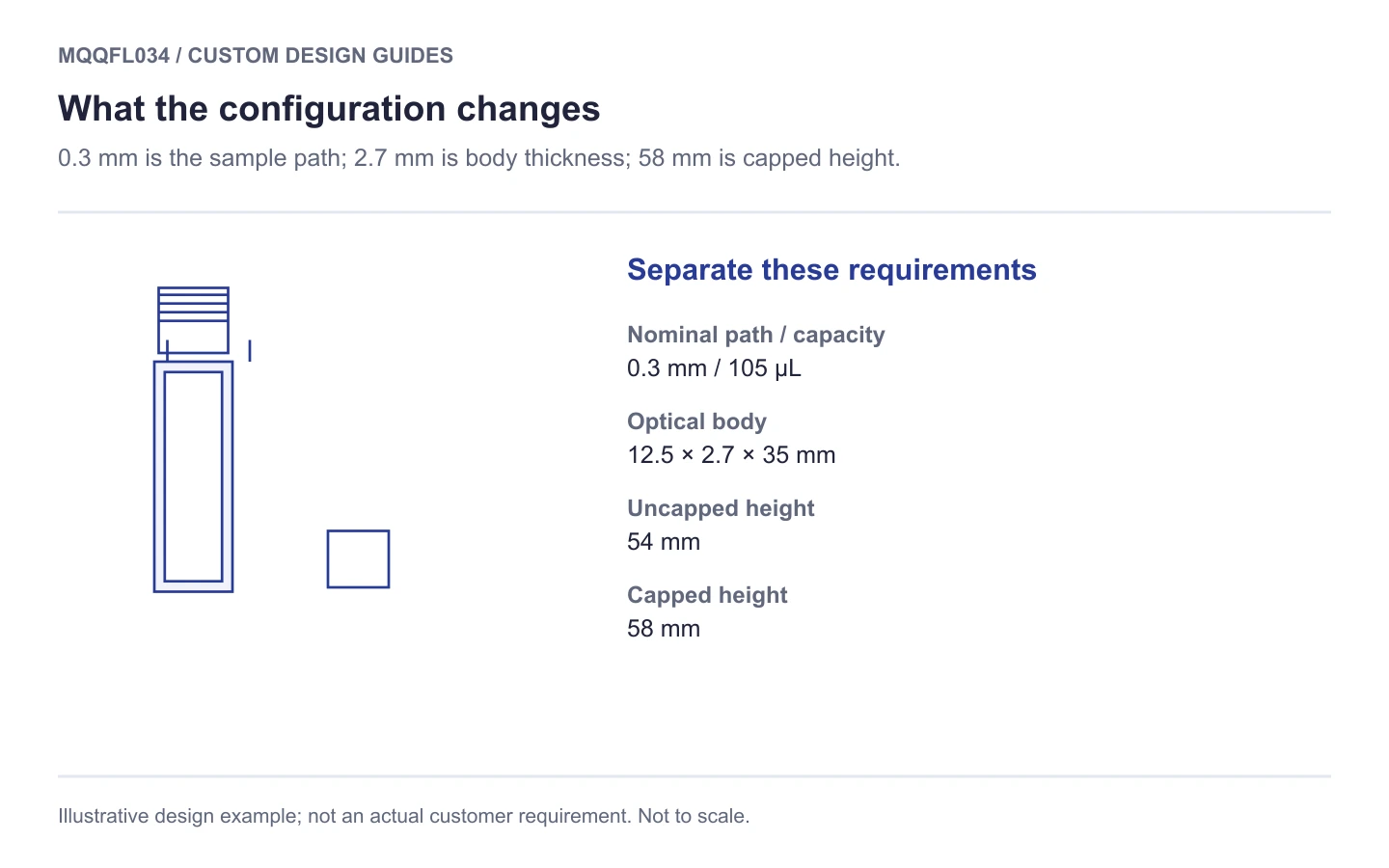
A very short path is an option to evaluate when a longer path puts absorbance outside the useful measurement range and dilution is undesirable. MQQFL034 combines a nominal 0.3 mm path and 105 µL capacity with a screw-top loading arrangement. This is an optical choice as well as a small-volume choice.
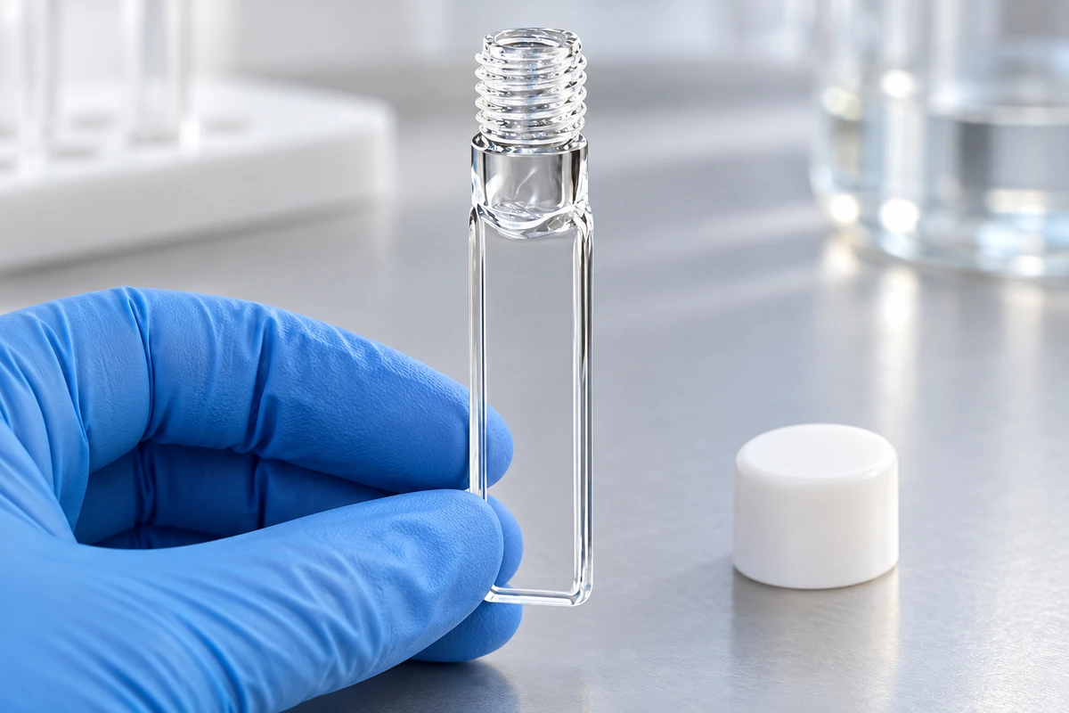
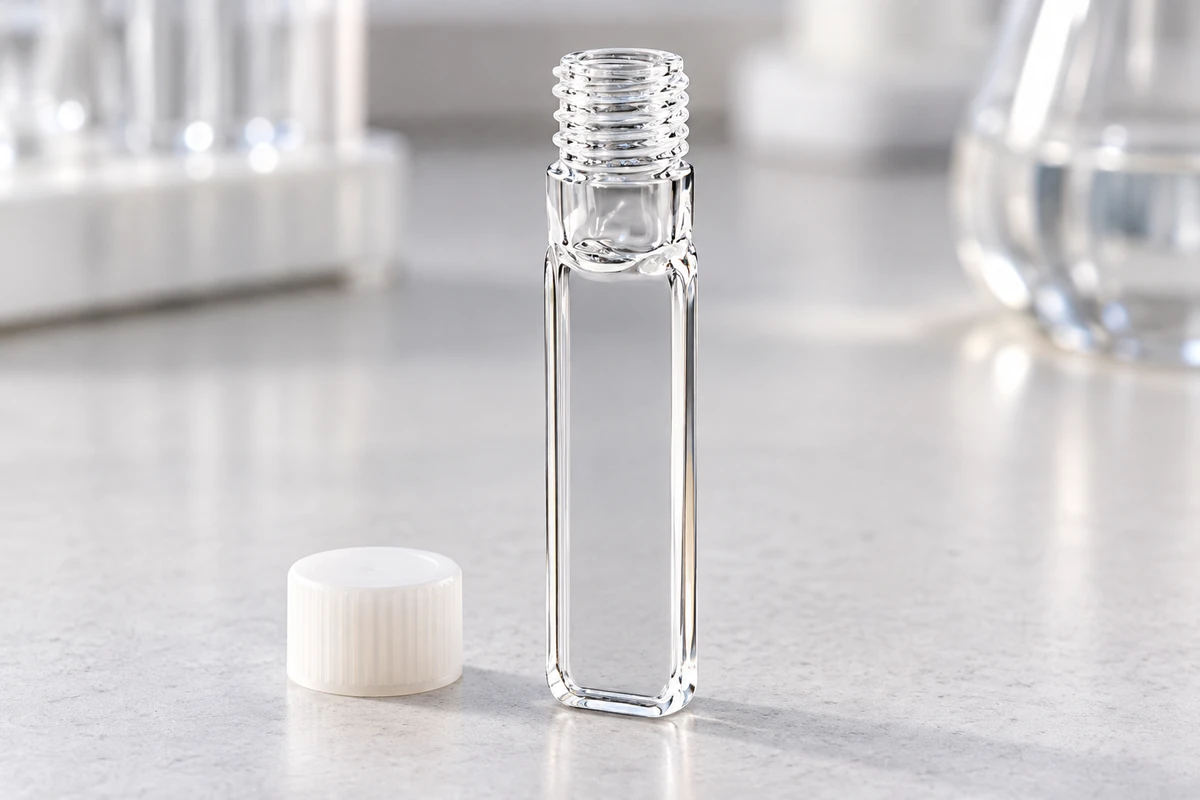
The lower optical body is 2.7 mm thick and 35 mm high. The larger M10 neck takes the uncapped height to 54 mm, or 58 mm with the cap. A compartment that accepts the thin body can still obstruct the closure or loading tool.
The listed configuration
View the selection schematic
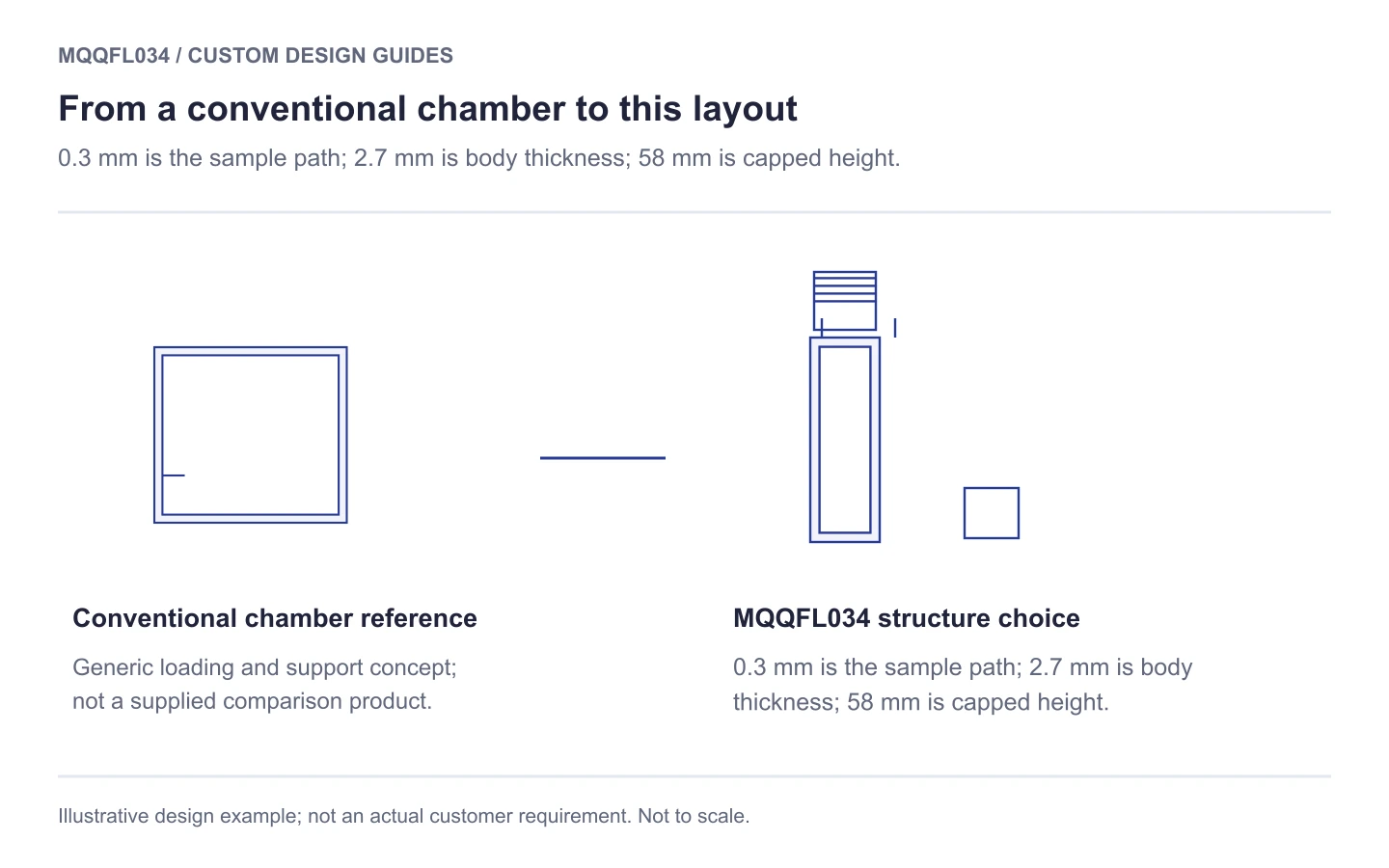
How the structure differs from a conventional cell
The thin sample layer and the loading opening no longer share the same outline. A larger neck above a thin body provides a different loading arrangement, but leaves a narrow region to fill and align with the beam. Under Beer–Lambert conditions, shortening the path reduces absorbance at fixed concentration and wavelength; finished-cell suitability still depends on the method.
Technical basis: IUPAC Gold Book: Beer–Lambert law. General relationship between absorbance and path length, under its stated conditions.
Keep the sample layer fixed while reviewing access
If the 0.3 mm path is required and only the cap clashes with the lid, identify the optical region as fixed. Show the permitted capped outline and the movement of the loading tool. We can review the neck and closure around those constraints.
If the path itself must change, specify the target and how it will be accepted. Body thickness, chamber geometry and closure clearance may need to change together. A grade label does not define the tolerance of a revised sample layer.
View a custom-design discussion sketch
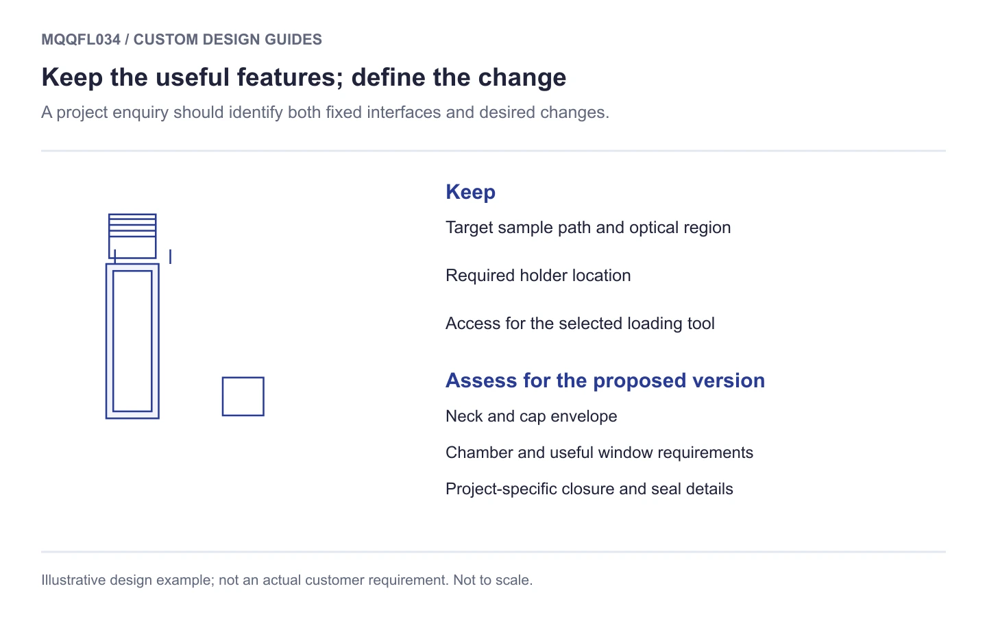
Three checks for the proposed setup
- Sample layer. State the required path and its dimensional or optical acceptance method.
- Upper clearance. Include the 58 mm capped height and loading/removal movement.
- Wetted closure. Specify any required cap or liner materials; the pictured cap material remains to be confirmed.
Check whether the thin region fills continuously
Plan loading, closing and emptying as one sequence, watching for bubbles or an unfilled area at the beam. Avoid forcing a tool into the narrow layer. Cleaning and any seal check must suit the actual medium and construction; the screw closure has no established pressure rating or verified gas-tightness in the available information.
What if the optical body fits but the cap is too high?
Send a section through the compartment showing the optical centre, maximum capped height and space for opening or removal. Identify the 0.3 mm path and useful optical region that must remain, so the closure can be reviewed without changing the measurement requirement unintentionally.
Engineering dimension reference
The reference records known external dimensions and configuration notes. Internal geometry, tolerances and operating limits still require a project-specific specification.
Open the engineering reference image
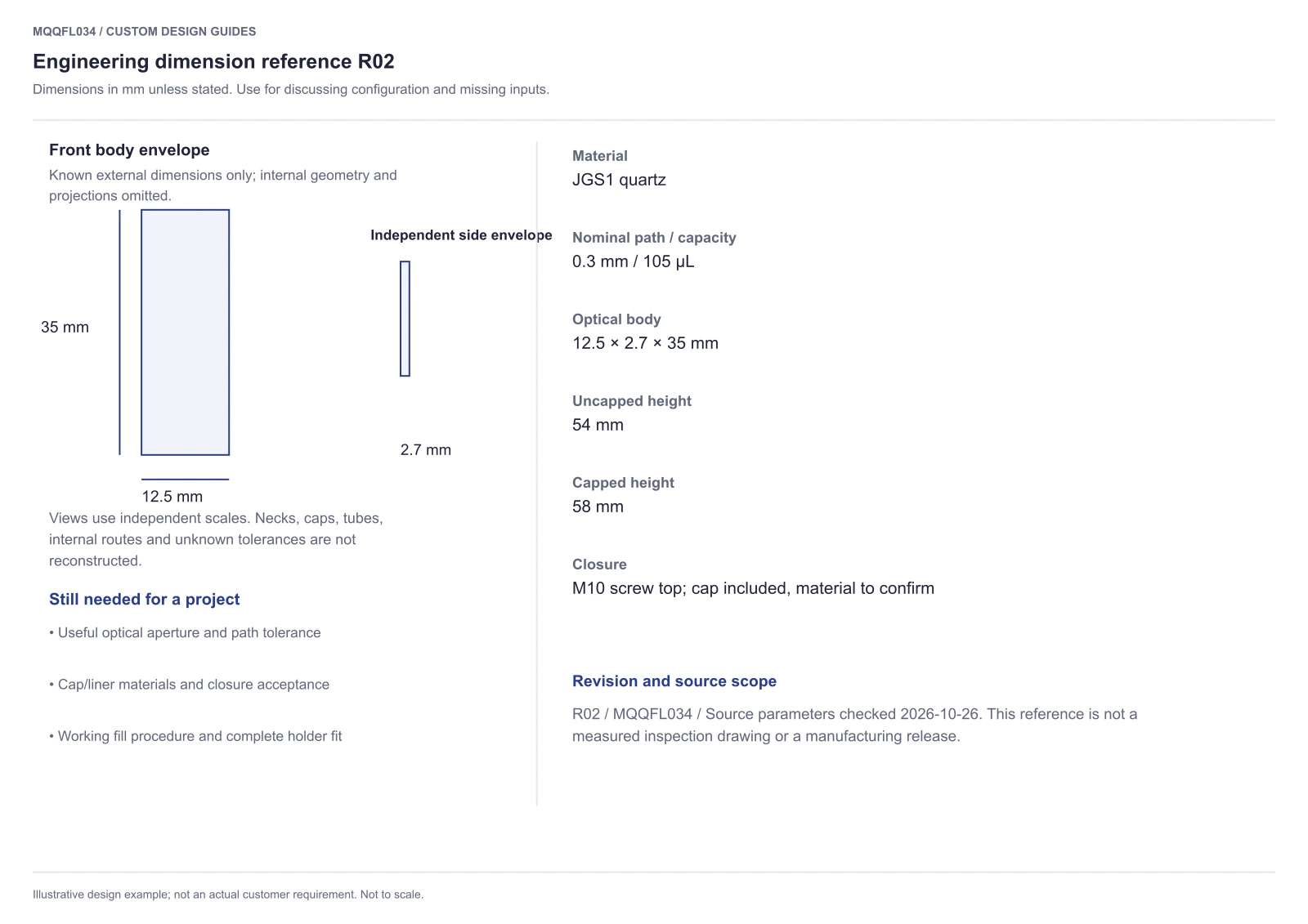
Download MQQFL034 engineering reference R02 (PDF). Illustrative design example; not an actual customer requirement.
Order this configuration or discuss a change
View MQQFL034 specifications and current pricing. Ask about availability and preparation or production time if you have a required delivery date.
For a modified version, attach a dimensioned drawing or labelled sketch. Contact MQ to review feasibility, quantity, inspection scope, price and timing for the proposed design.
Copy a starting brief for your enquiry
Reference SKU: MQQFL034
Required path and acceptance ___; fixed optical region ___; capped height limit ___; loading tool ___; medium/temperature and wetted closure ___; quantity ___.
Attach your marked drawing and note any required inspection or documentation. Include the destination and target date so preparation, transport and customs can be discussed separately.
Send your sketch and requirements. Identify fixed interfaces and proposed changes.
Configuration and technical references
Configuration source: MQQFL034 configuration information. Listed parameters reviewed 26 October 2026.
Prepared for MachinedQuartz product selection and custom enquiries. MachinedQuartz is a US-based supplier established in New Mexico, USA, in 2026. Contact MQ. Custom cuvette enquiries · More design guides.


Recent Comments