
Perforated Quartz Plates: Turning Separate Parts into a Clear Assembly Brief
Custom Design Guides · MQQCU008
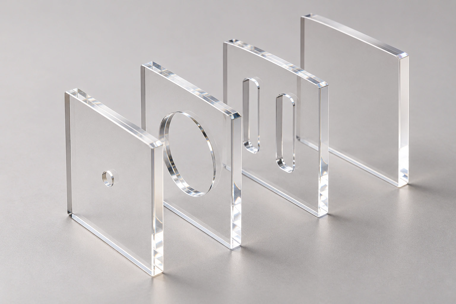
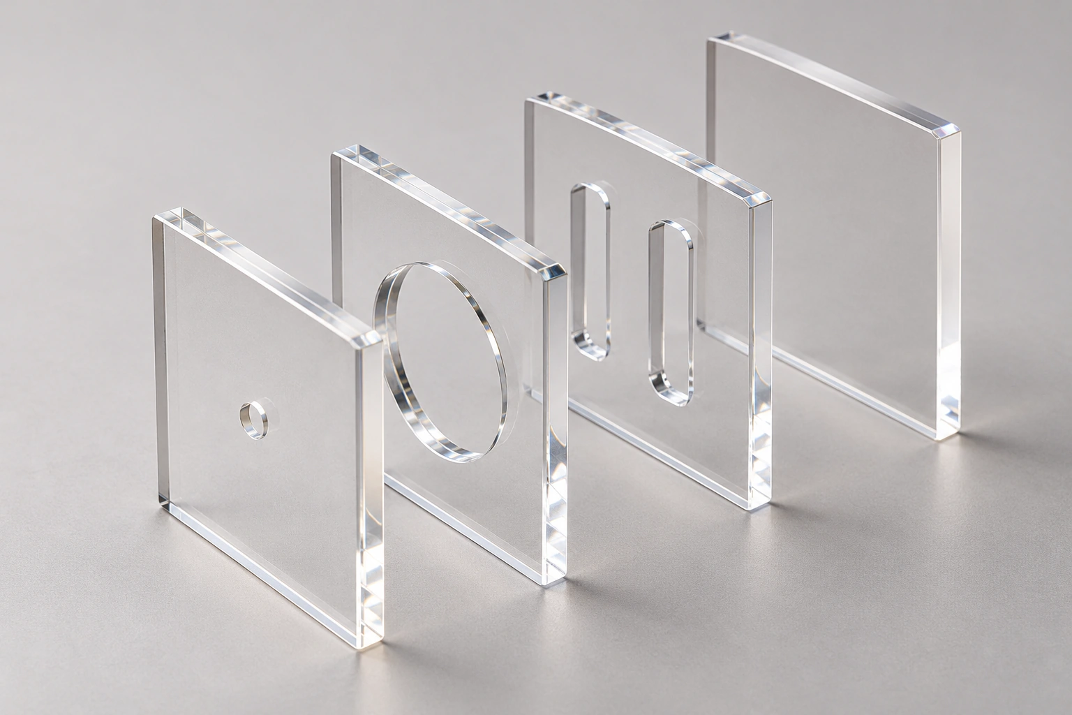
The MQQCU008 reference illustrates quartz plates with different openings, including circular and slotted features. These visible examples are a starting point for discussing individual custom parts.
The picture does not establish that every illustrated plate is supplied together or that they form a completed sealed cell. The bill of materials and assembly arrangement need their own definition.
In this guide: Configuration · Design comparison · Give each plate a part identifier · Locate openings from the mating surfaces · Define how the proposed assembly is retained · Inspect the parts against their own requirements · Enquiry
The configuration discussed here
What changes from the simpler form?
Individual holes and slots turn plain quartz plates into mating parts. The next design step is an explicit parts and assembly definition, not an assumption that the illustrated pieces form a supplied sealed cell.
Give each plate a part identifier
Show the outline and thickness of each proposed plate separately. Identify the faces, hole centres, slots and any required orientation mark on its own drawing.
This gives each requested part an explicit specification. It also makes clear which plain or perforated parts are needed and in what quantity.
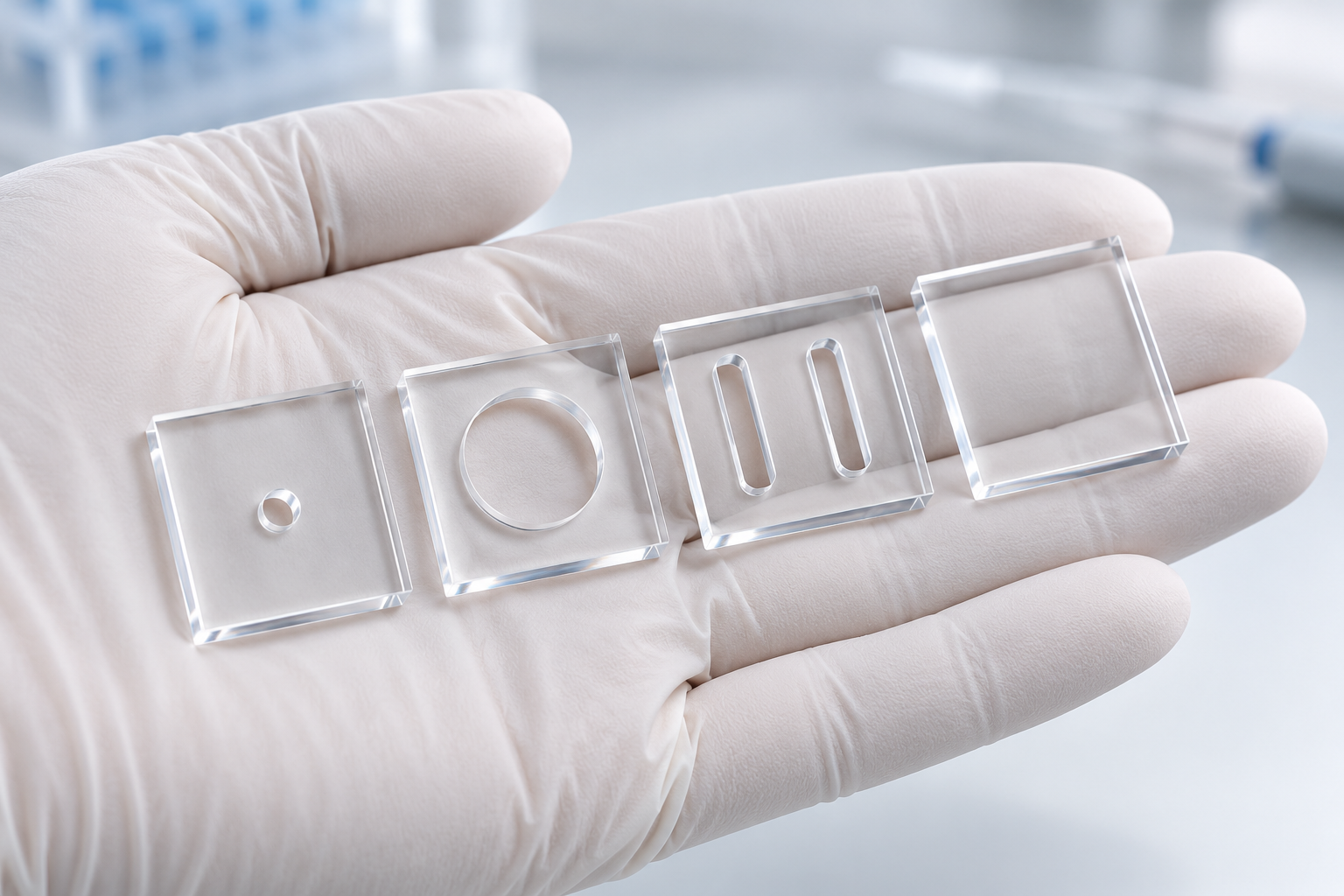
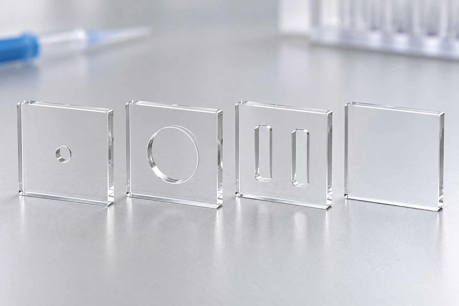
The illustration distinguishes four 10 × 10 mm plate examples: a 2 mm round opening, a 7 mm round opening, two 2 × 6 mm slots and a plain plate. Their illustrated thicknesses are 1, 2, 1 and 1 mm respectively. These are drawing examples to discuss, not a confirmed package or inspection result.
Locate openings from the mating surfaces
A hole or slot needs a position reference as well as a size. Show the part that passes through it, the required clearance and the direction of insertion.
If an opening is near an optical region, mark the clear area and the allowed surrounding contact. The drawing should make both interfaces visible rather than assuming they do not interact.
Define how the proposed assembly is retained
If the parts are intended to work together, provide an assembly section and identify contact, locating and retention requirements. A loose-parts image does not establish a bonding process or a completed containment boundary.
For example, a custom access plate may be useful while retaining other parts in an existing fixture. MQ needs the actual mating references and the parts to retain before reviewing that option.
Inspect the parts against their own requirements
Specify critical outline, thickness, opening size and position requirements for each item. Add any optical-face or edge requirements where the method needs them.
Any joining, seal or assembled performance requirement should be listed separately with an agreed method. That gives a clearer acceptance basis than describing a collection of plates as a finished custom cell.
Structure reference and specification points
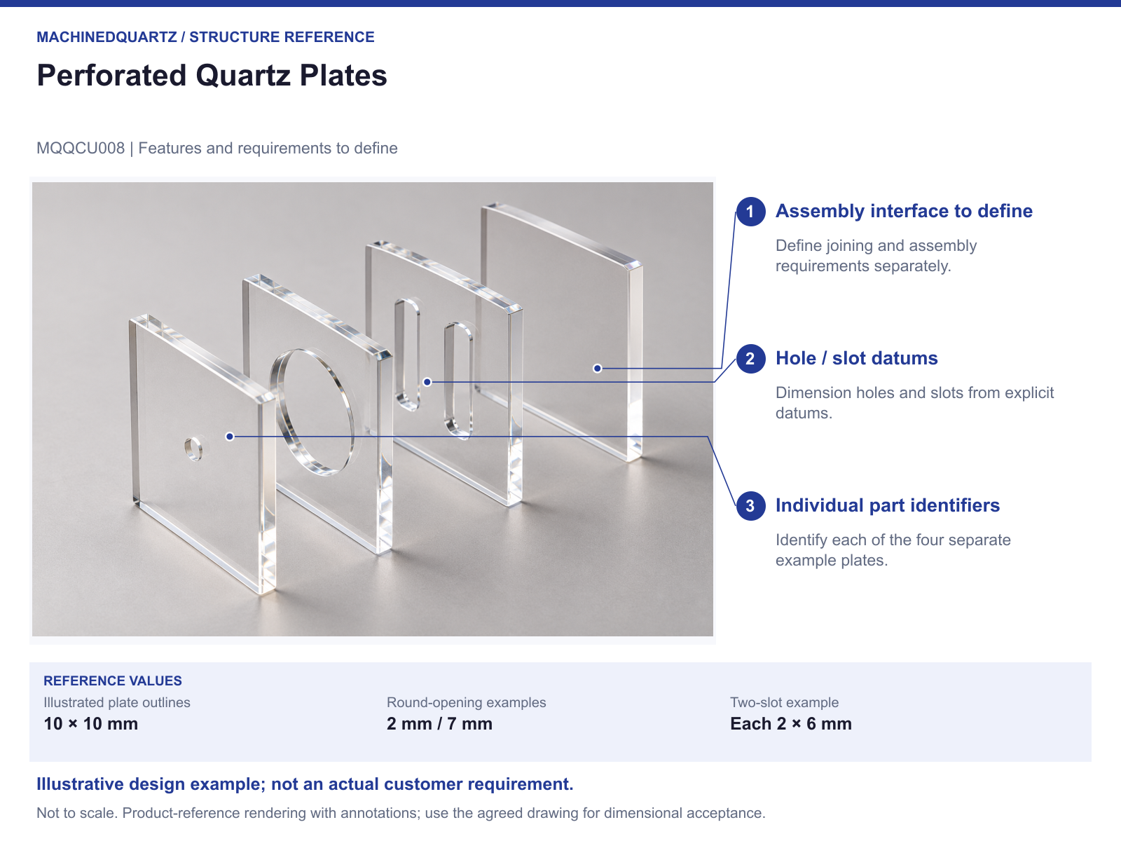
Download the structure reference (PDF)
Does the reference image show a complete supplied cell?
It illustrates differing quartz parts. Confirm the individual supplied items and any assembly, joining or sealing requirement in the quotation.
Send a drawing or the mating-part details
Send a numbered parts list with the mating section. MQ can review perforated quartz pieces without assuming a supplied assembly or manufacturing route.
- Numbered individual part drawings and quantities
- Hole and slot sizes, positions and mating items
- Required clear optical areas
- Assembly section and retention requirements
- Part-level and assembled acceptance scope
Modified designs are reviewed for the project. The drawing, supplied parts, quantity, inspection scope, price and preparation or production time are agreed in the quotation.
Details to settle for the ordered configuration
Supplied set, dimensions, joining process, containment and optical performance require an agreed design and quotation.


Recent Comments