
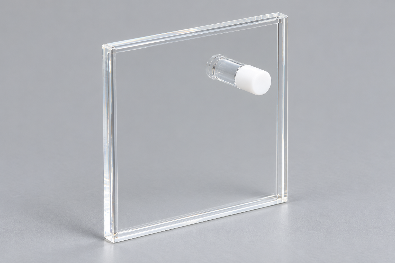
1 / 50 mm Dual-Path Quartz Cuvette: Two Views of the Same Sample
CUSTOM DESIGN GUIDE · C016SS
C016SS spreads a sample through a broad, thin quartz chamber. Its recorded paths are 1 mm through the thickness and 50 mm across the chamber. This gives two very different sample distances in one cell, provided the holder leaves the chosen viewing directions accessible.
Use and purpose · Specifications · In practice · Custom example · Buy or enquire
One chamber, two path directions
The recorded internal space is 50 × 50 × 1 mm, inside a 53 × 53 × 4 mm body. Looking through the thin direction and looking across the chamber are different optical arrangements around the same sample space. The path values describe those directions rather than separate cells.
In absorption work, path length is one way to change absorbance without changing concentration. The shorter and longer directions therefore provide a useful design comparison. They do not establish interchangeable measurement conditions: beam position, filled region and instrument geometry still belong to each arrangement. [1]
C016SS configuration
The broad face changes how the cell is supported
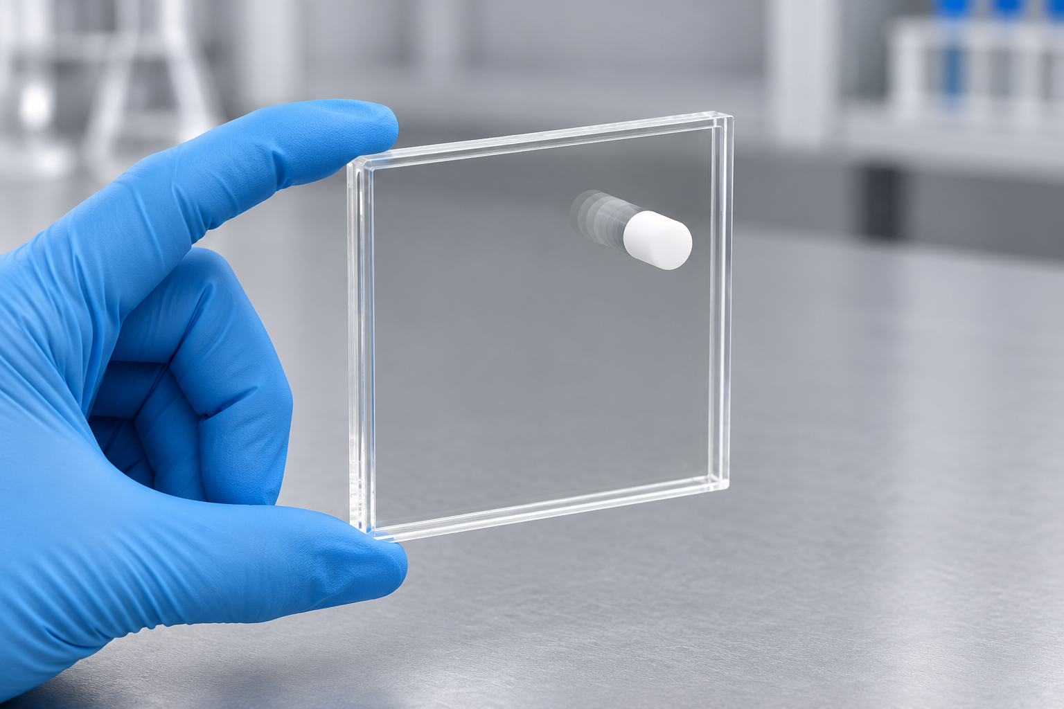
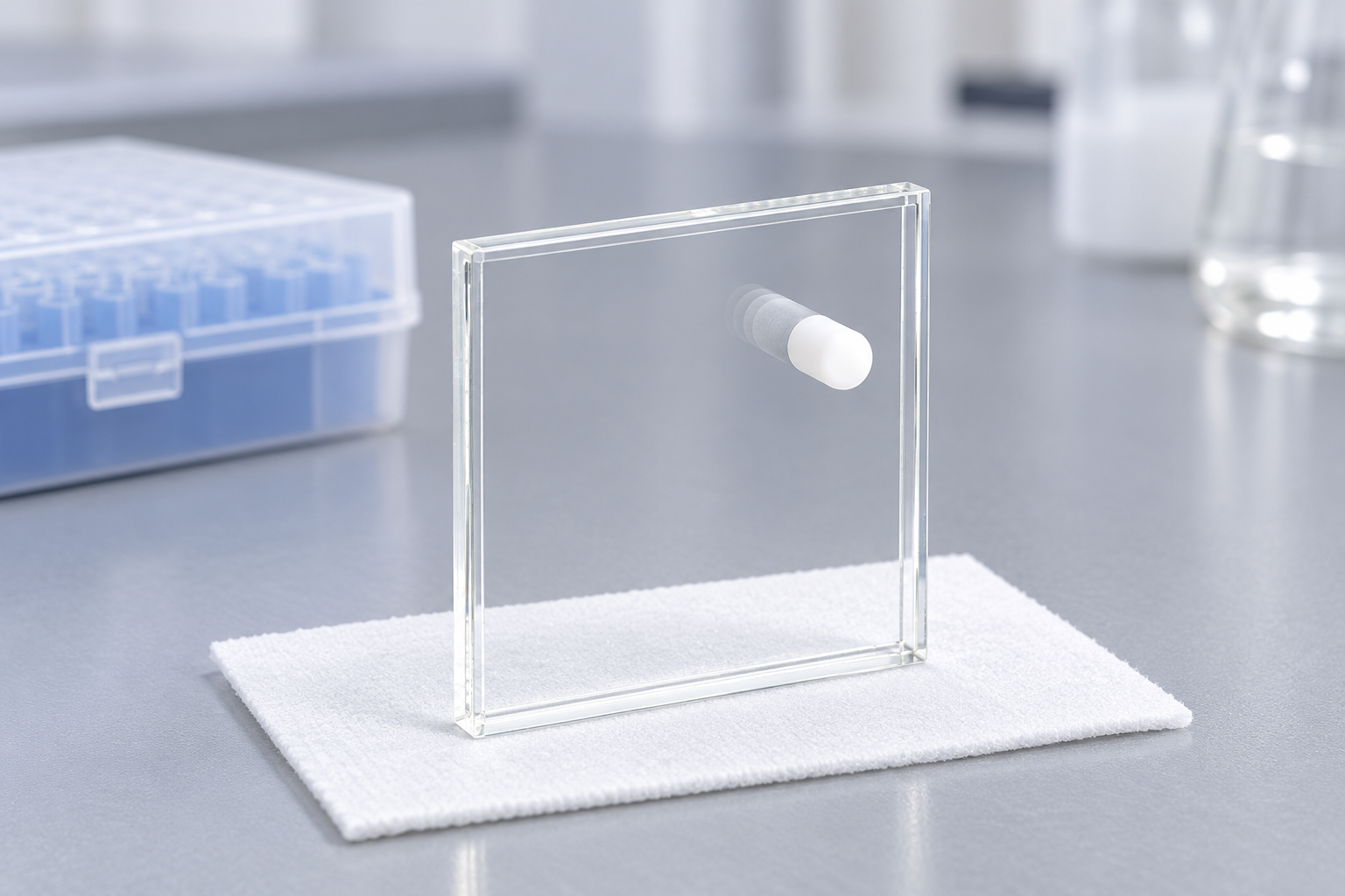
An upright square cuvette can often be located around a small base. This plate-like body occupies a wider area, so its support needs to leave the relevant faces and edges exposed. The listed six-face optical layout describes the bare cell; a holder determines which directions remain available in use.
For a setup using both paths, a shared support datum is particularly useful. It relates each beam direction to the same chamber, instead of treating the two views as unrelated installations.
Orientation affects filling as well as viewing
The stoppered opening gives access to the chamber. Space for filling and removing the stopper belongs beside the supported body. The nominal 2 mL capacity is a configuration value, while the working liquid level depends on the cell's orientation and the beam location.
A proposed procedure can therefore describe how the cell is filled, placed and turned between views. That sequence may suggest a change to the border or holder before any change to the sample chamber is necessary.
A custom example: expose both paths around the same support
ILLUSTRATIVE DESIGN EXAMPLE
Suppose an instrument needs the 1 mm view and a view across the 50 mm direction, but a retaining edge covers one route. A proposed border or holder interface can keep the chamber and move that contact away from the optical paths. The useful sketch shows both views and the stopper in one orientation reference.
Order the listed configuration or discuss a change
View C016SS and current pricing. For a custom version, send a labelled sketch that separates the features to retain from the changes you want.
Reference C016SS and mark the required viewing directions, filled region, support contacts and stopper access. Identify the chamber dimensions to keep and any border changes. Add sample conditions, quantity, destination and requested date.


Recent Comments