
Quartz Flow Cuvette with a Three-Way Valve: Managing Sample Access
CUSTOM DESIGN GUIDE · C104WE1
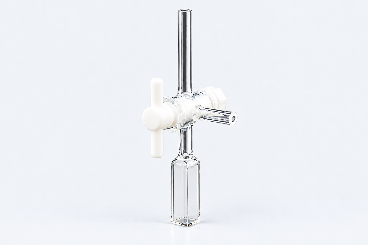
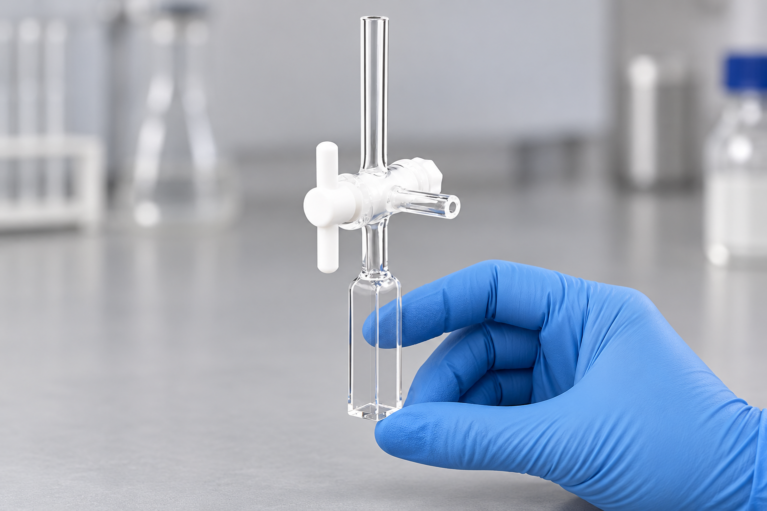
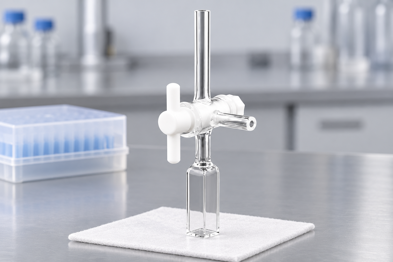
The C104WE1 reference combines a square-bottom optical body with a tall upper neck, three-way valve and side connection. Its nominal path is 10 mm and capacity 3.5 mL. The design brings valve operation into the sample-handling routine while leaving the lower cell as the observation region.
Use and purpose · Specifications · In practice · Custom example · Buy or enquire
What the valve adds to a cuvette
An open-top cuvette is usually approached directly for filling and retrieval. Adding an upper valve creates a different route into the proposed fluid arrangement. The relevant design questions become where the lines attach, which route is used at each step and where the valve can be operated.
The three-way description identifies the valve form, but the intended port assignments belong to the assembly. A labelled route sketch can describe loading, exchange or isolation steps without assuming a flow direction from the product photograph.
C104WE1 configuration
Keep the lower optical body as a stable reference
The reference has a square bottom and four-way optical access. The bottom and side contacts can locate the measurement region independently of the space occupied by the upper valve. That separation is useful when adapting a connected cell to a holder originally designed around an upright cuvette.
The nominal 3.5 mL capacity describes the chamber configuration. Connected tubing and the operating sequence add their own liquid requirements, so the cell capacity alone is not a sample budget for the complete route.
Design for operating the valve, not just closing the compartment
A stationary outline can miss the part of the handle's sweep needed during use. The side connection, upper connection and hand or tool operating the valve also approach from different directions. A layout that shows those movements is more useful than an overall height alone.
This form is a starting point when upper valve access serves the procedure. Where that access is unnecessary or cannot fit the compartment, a simpler port or closure arrangement may better match the task.
A custom example: turn the side line away from a bracket
ILLUSTRATIVE DESIGN EXAMPLE
Suppose the square-bottom cell fits the holder, but a side line meets an adjacent bracket. A proposed upper assembly can retain the 10 mm optical region while changing the connection orientation. The drawing keeps the required valve movements and both line approaches visible, rather than moving the optical body simply to make the line fit.
Order the listed configuration or discuss a change
View C104WE1 and current pricing. For a custom version, send a labelled sketch that separates the features to retain from the changes you want.
Reference C104WE1 with a labelled valve-route sketch, the holder contacts and the space available around the upper assembly. Identify the optical features to retain. Add sample and operating conditions, quantity, destination and requested date.


Recent Comments