
ITO Conductive Glass: Separating the Optical Area from Electrical Contacts
Custom Design Guides · MQOGS094
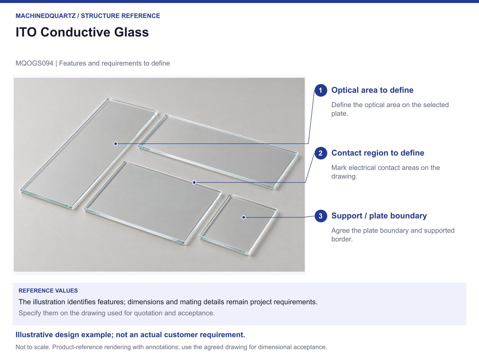
A conductive glass plate has more than one working region. MQOGS094 is the custom ITO-glass reference for discussing where light passes, where electrical contact is made and where the plate can be supported.
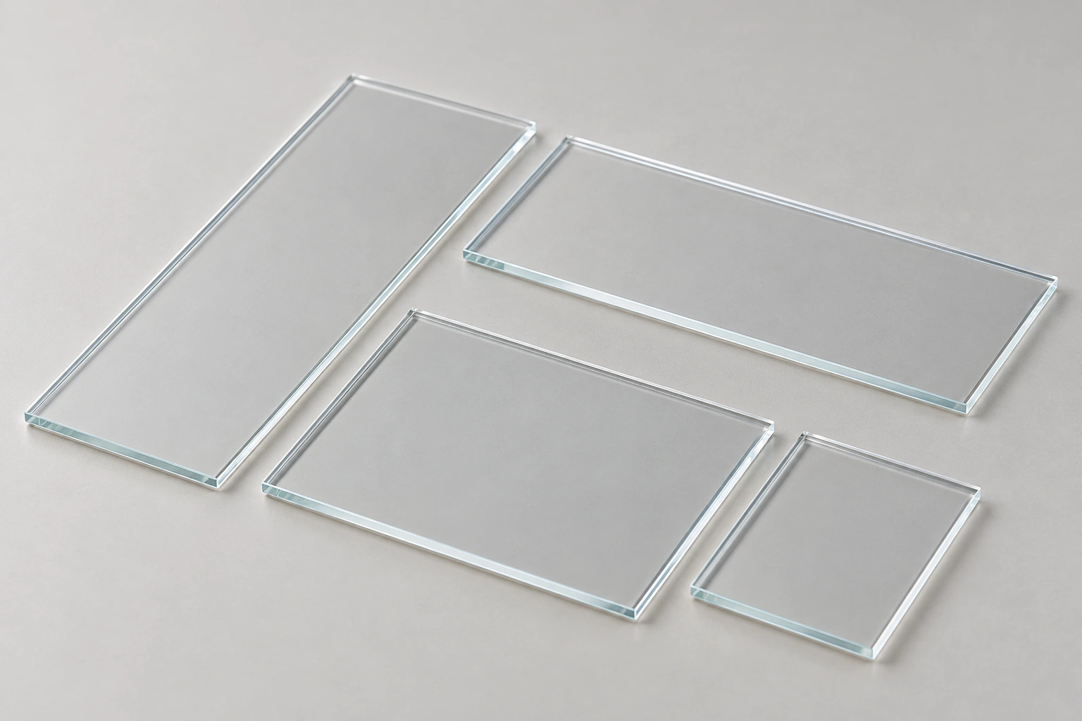
The illustration shows the product type. Plate size, coating pattern, sheet resistance and optical transmission are specification items to define for the proposed design.
In this guide: Configuration · Design comparison · Draw the active area before the outline · Specify electrical and optical requirements together · A custom version needs a defined coating side · Plan handling around the functional surface · Enquiry
The configuration discussed here
What changes from the simpler form?
ITO introduces an electrical function to a transparent plate concept. The plate now needs an electrical-contact region and acceptance criteria alongside its optical area and mechanical support.
Draw the active area before the outline
Mark the region through which the experiment needs optical access. Then add the plate boundary, support contacts and the space available for an electrical connection. A simple plan view can reveal a conflict that a size-only enquiry misses.
Distinguish the active optical area from an uncoated edge or contact area if either is required. The reference does not establish that such a pattern is already present.
Specify electrical and optical requirements together
Give the required sheet resistance or other electrical acceptance measure and how it will be assessed. For the optical requirement, identify the wavelength range, measurement arrangement and acceptance criterion.
A transparent appearance is not a transmission measurement. Likewise, the term ITO does not establish the electrical result of a particular plate or contact arrangement.
A custom version needs a defined coating side
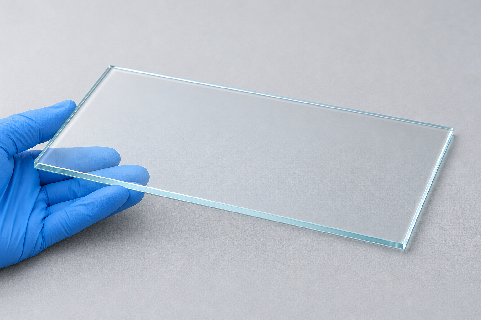
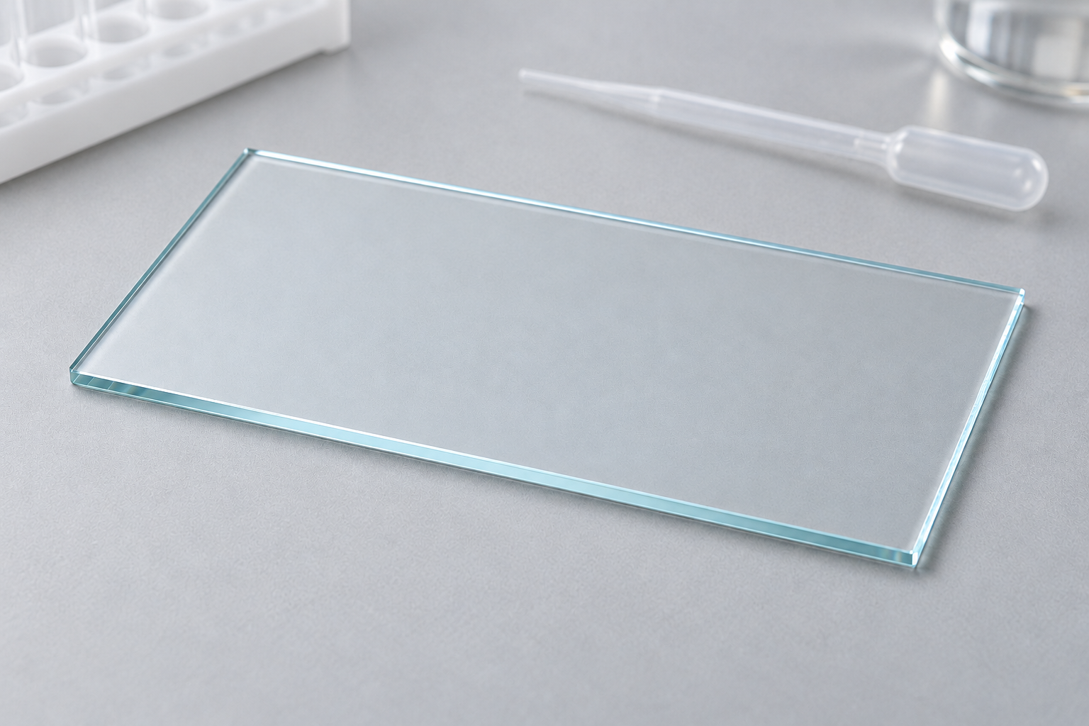
For example, a customer may need a plate that fits an existing holder while leaving an accessible contact edge. Mark the coated face, the contact position and the region the holder must leave clear.
If a pattern, cut-out or edge treatment is proposed, supply a drawing rather than treating the illustration as a specification. Feasibility and the inspection scope can then be reviewed for that design.
Plan handling around the functional surface
Identify the surfaces that may be touched or contacted by the fixture and describe the relevant sample chemicals and conditions. The actual compatibility and cleaning requirements should follow the proposed use.
Agree substrate dimensions, coating acceptance, packaging and any requested records. These are the details that turn an ITO material request into an inspectable ordered part.
Structure reference and specification points
Download the structure reference (PDF)
Can the family image be used to choose a resistance or plate thickness?
No. Those values are not established by the image. Provide the plate geometry, electrical target and optical conditions for a configuration-specific review.
Send a drawing or the mating-part details
Send a marked plan view showing the optical and electrical regions. MQ can then review the plate as a functional part rather than an unspecified piece of clear glass.
- Plate outline, thickness and substrate requirements
- Active optical area and wavelength conditions
- Coated face, pattern and contact locations
- Electrical acceptance and measurement method
- Fixture contacts, sample conditions and quantity
Modified designs are reviewed for the project. The drawing, supplied parts, quantity, inspection scope, price and preparation or production time are agreed in the quotation.
Details to settle for the ordered configuration
No particular plate dimensions, resistance, transmission, pattern or compatibility result is established for this custom reference.


Recent Comments