
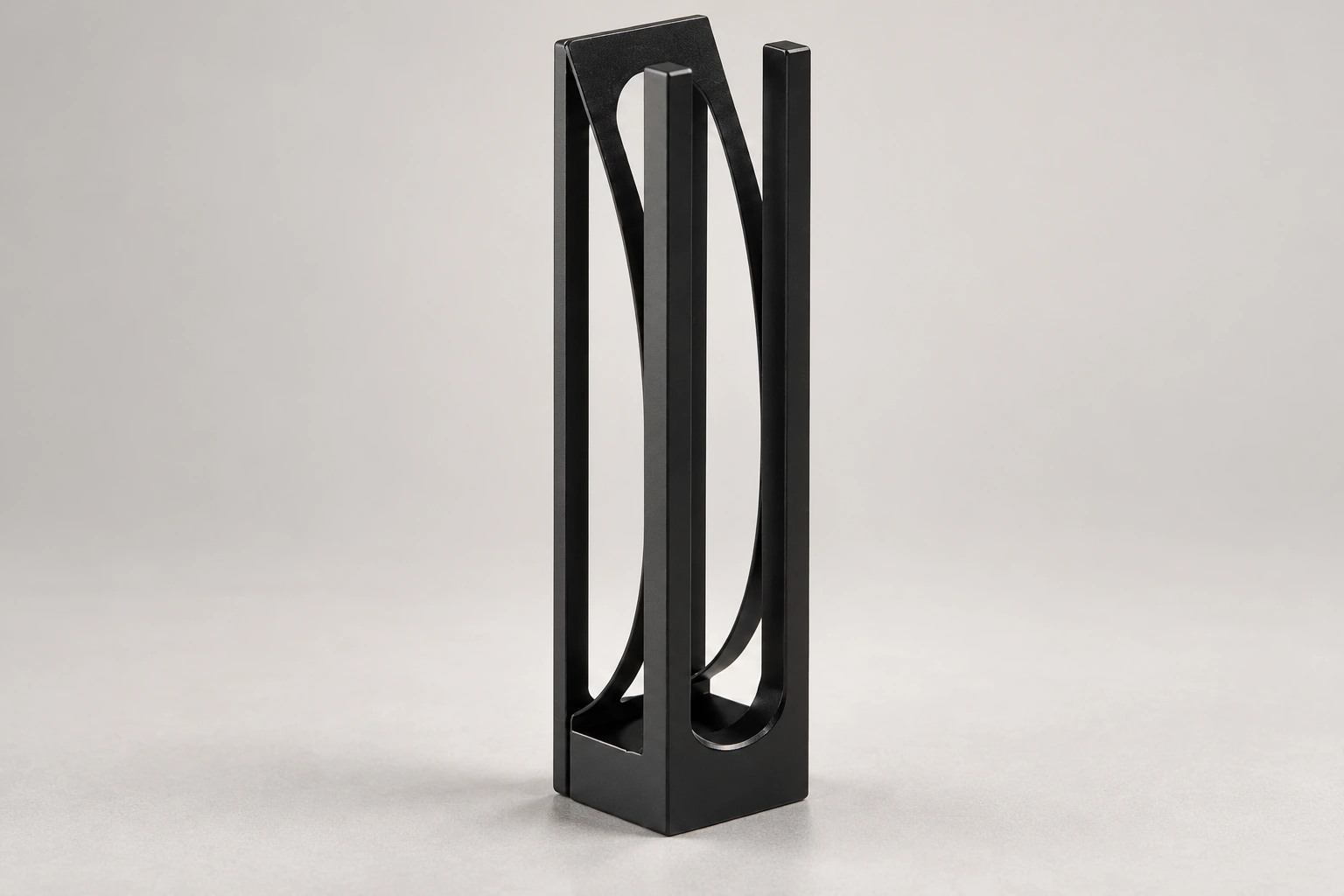
Short-Path Cuvette Adapter: Supporting a Thin Cell without Blocking the Beam
Custom Design Guides · MQACC002
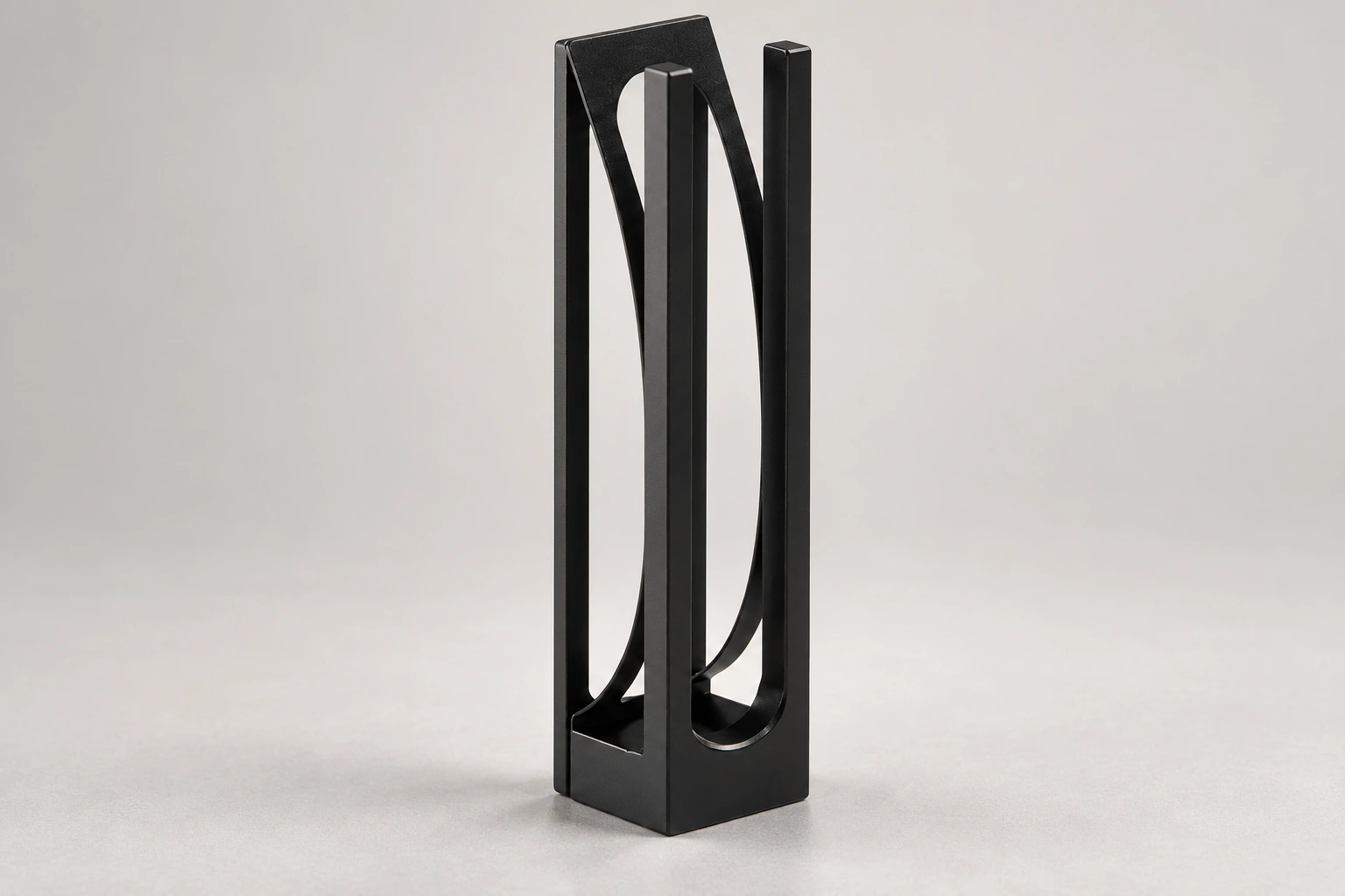
A thin cuvette may need an adapter to sit in a larger holder. MQACC002 is the aluminium-alloy support reference with an approximately 12.5 × 12.5 × 50 mm outside envelope and an open region for optical access.
The adapter does not change the liquid path inside the cuvette. Its job in the proposed setup is mechanical support and location while leaving the required window area clear.
In this guide: Configuration · Design comparison · Define three fits instead of one · Place the clear opening around the actual beam · Changing the adapter can preserve the cell · Use a trial fit to answer the relevant questions · Enquiry
The configuration discussed here
What changes from the simpler form?
An adapter changes the support interface around an existing thin cell rather than changing the cell's sample gap. The result needs three matched references: cell-to-adapter, adapter-to-holder and optical clearance.
Define three fits instead of one
First describe how the cell meets the adapter. Then describe how the adapter meets the instrument holder. Finally, show the optical region that must remain unobstructed. One outside dimension cannot establish all three relationships.
The cell's thickness, contact faces and insertion direction belong in the mating drawing. A nominal sample path is not automatically the outside thickness the adapter must accept.
Place the clear opening around the actual beam
Give the beam direction and its required position relative to the holder datum. The adapter opening needs to leave the relevant cell window clear; a large-looking aperture is not evidence of alignment with a particular instrument.
For example, a support may fit the holder while locating a small sample region too high or too low. Include the cell and holder references so the optical position can be reviewed rather than inferred from adapter height.
Changing the adapter can preserve the cell
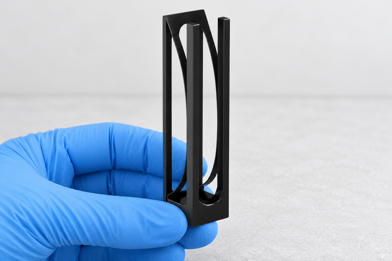
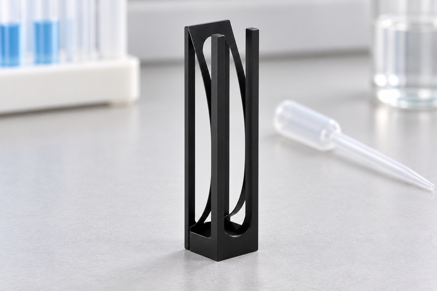
If an existing cuvette is suitable for the method but awkward to support, a custom adapter is a different route from changing the cell body. Mark the cell geometry to retain and the holder contacts the adapter needs to provide.
The proposed slot, opening and locating surfaces can then be discussed together. MQ would need the actual cell and holder dimensions before a compatibility or positioning claim could be made.
Use a trial fit to answer the relevant questions
A proposed check should include insertion, location, removal and optical clearance with the actual parts. Identify which contacts and reference positions matter, rather than using a broad compatible-path range as the acceptance test.
Any required machining tolerance, finish or material record should be agreed for the adapter. A storage-rack use and an instrument optical-holder use are not interchangeable tasks.
Structure reference and specification points
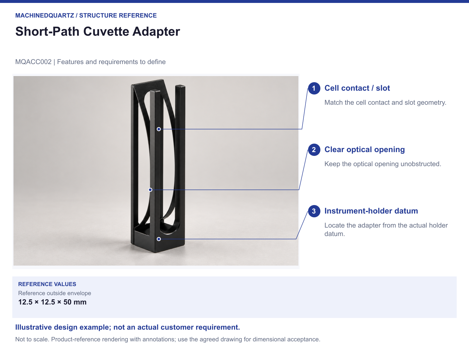
Download the structure reference (PDF)
Will it make any short-path cuvette fit a standard holder?
No universal fit is established. The cell outside geometry, adapter slot, holder interface and optical position must be checked as a set.
Send a drawing or the mating-part details
Send the cell and holder sections together. MQ can review an adapter that supports the selected cuvette without assuming a change to the sample path.
- Cell outside dimensions and allowed contact regions
- Holder opening, locating datum and insertion route
- Beam direction and clear-window position
- Adapter slot, support and removal requirements
- Quantity, dimensional tolerance and proposed fit check
Modified designs are reviewed for the project. The drawing, supplied parts, quantity, inspection scope, price and preparation or production time are agreed in the quotation.
Details to settle for the ordered configuration
Exact slot dimensions, positioning result, optical clearance and instrument compatibility require confirmation.


Recent Comments